
How to Use PCM1808 Audio Stereo ADC Single-Ended Analog-Input Decoder 24bit Amplifier Board: Examples, Pinouts, and Specs
 Design with PCM1808 Audio Stereo ADC Single-Ended Analog-Input Decoder 24bit Amplifier Board in Cirkit Designer
Introduction
The PCM1808 is a high-performance stereo analog-to-digital converter (ADC) designed for audio applications. It features a 24-bit resolution and supports single-ended analog inputs, making it ideal for capturing high-quality audio signals. This component is widely used in audio recording, signal processing, and digital audio systems due to its low noise and high dynamic range.
Common applications include:
- Audio recording devices
- Digital signal processing (DSP) systems
- Home theater systems
- Audio measurement equipment
- Embedded systems requiring audio input
Explore Projects Built with PCM1808 Audio Stereo ADC Single-Ended Analog-Input Decoder 24bit Amplifier Board
 Open Project in Cirkit Designer
 Open Project in Cirkit Designer
 Open Project in Cirkit Designer
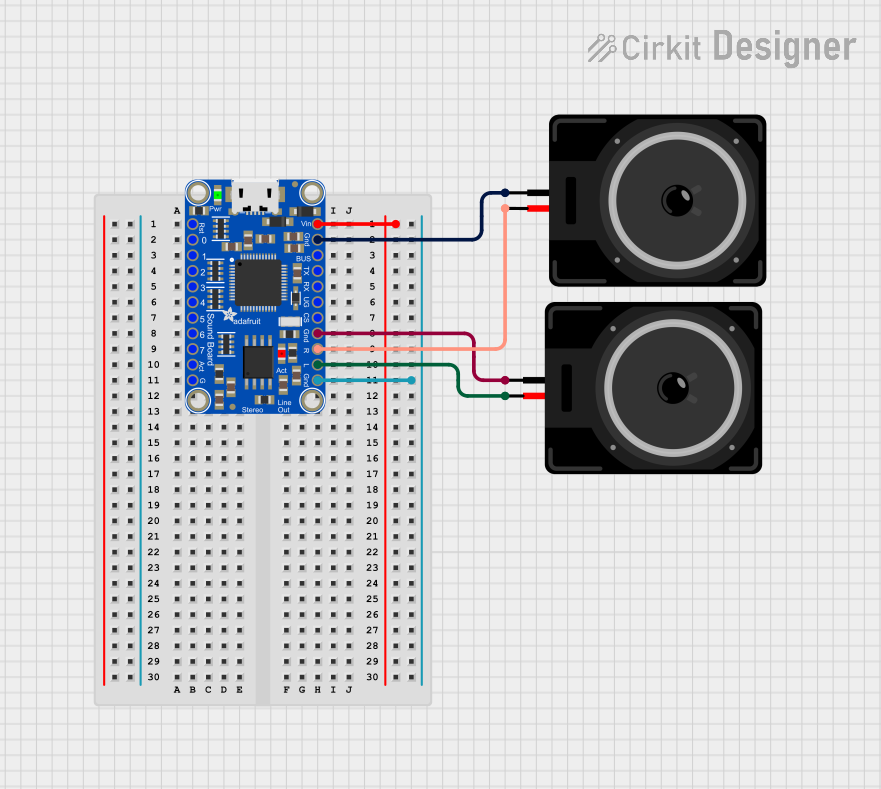 Open Project in Cirkit Designer
Explore Projects Built with PCM1808 Audio Stereo ADC Single-Ended Analog-Input Decoder 24bit Amplifier Board
Open Project in Cirkit DesignerOpen Project in Cirkit DesignerOpen Project in Cirkit DesignerOpen Project in Cirkit DesignerTechnical Specifications
The PCM1808 ADC board is built around the Texas Instruments PCM1808 IC and includes supporting components for easy integration into projects. Below are the key technical details:
Key Features
- Resolution: 24-bit
- Sampling Rate: Up to 96 kHz
- Input Type: Single-ended analog input
- Dynamic Range: 99 dB (typical)
- Signal-to-Noise Ratio (SNR): 99 dB
- Power Supply Voltage: 3.3V or 5V (depending on board design)
- Digital Output Format: I²S or Left-Justified
- Operating Temperature Range: -25°C to 85°C
Pin Configuration and Descriptions
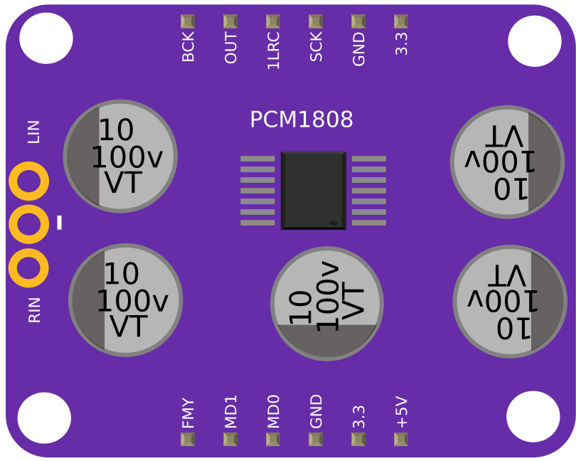
The PCM1808 board typically includes a header for easy connection. Below is the pinout:
| Pin Name | Description |
|---|---|
| VCC | Power supply input (3.3V or 5V, depending on board) |
| GND | Ground |
| L_IN | Left channel analog input |
| R_IN | Right channel analog input |
| BCK | Bit clock for I²S interface |
| LRCK | Left-right clock for I²S interface |
| DATA | Digital audio data output (I²S format) |
| MCLK | Master clock input (optional, depending on board) |
Usage Instructions
How to Use the PCM1808 in a Circuit
- Power Supply: Connect the VCC pin to a 3.3V or 5V power source (check your board's specifications) and the GND pin to ground.
- Analog Inputs: Connect the left and right analog audio signals to the L_IN and R_IN pins, respectively. Ensure the input signal levels do not exceed the maximum input voltage (typically 2.1Vpp).
- Digital Interface: Connect the BCK, LRCK, and DATA pins to the corresponding pins on your microcontroller or DSP. If required, provide an external master clock (MCLK).
- I²S Configuration: Configure your microcontroller or DSP to receive I²S data at the desired sampling rate and bit depth.
Important Considerations
- Use decoupling capacitors near the power supply pins to reduce noise.
- Ensure proper grounding to minimize interference and noise in the audio signal.
- If using an Arduino UNO, note that it does not natively support I²S. You may need an external I²S interface or use a microcontroller with built-in I²S support (e.g., ESP32 or STM32).
Example Code for ESP32
Below is an example of how to interface the PCM1808 with an ESP32 using the I²S protocol:
#include <driver/i2s.h>

// I²S configuration for PCM1808
#define I2S_NUM         I2S_NUM_0  // Use I²S peripheral 0
#define I2S_BCK_PIN     26         // Bit clock pin
#define I2S_LRCK_PIN    25         // Left-right clock pin
#define I2S_DATA_PIN    22         // Data output pin

void setup() {
  // Configure I²S interface
  i2s_config_t i2s_config = {
    .mode = I2S_MODE_MASTER | I2S_MODE_RX, // Master mode, receive data
    .sample_rate = 44100,                  // Sampling rate: 44.1 kHz
    .bits_per_sample = I2S_BITS_PER_SAMPLE_24BIT, // 24-bit resolution
    .channel_format = I2S_CHANNEL_FMT_RIGHT_LEFT, // Stereo format
    .communication_format = I2S_COMM_FORMAT_I2S,  // I²S standard
    .intr_alloc_flags = 0,                 // No specific interrupt flags
    .dma_buf_count = 8,                    // Number of DMA buffers
    .dma_buf_len = 64                      // Length of each DMA buffer
  };

  // Configure I²S pins
  i2s_pin_config_t pin_config = {
    .bck_io_num = I2S_BCK_PIN,  // Bit clock pin
    .ws_io_num = I2S_LRCK_PIN,  // Left-right clock pin
    .data_out_num = -1,         // Not used for PCM1808
    .data_in_num = I2S_DATA_PIN // Data input pin
  };

  // Install and start I²S driver
  i2s_driver_install(I2S_NUM, &i2s_config, 0, NULL);
  i2s_set_pin(I2S_NUM, &pin_config);
}

void loop() {
  // Buffer to store audio data
  uint8_t audio_data[128];
  size_t bytes_read;

  // Read audio data from PCM1808
  i2s_read(I2S_NUM, audio_data, sizeof(audio_data), &bytes_read, portMAX_DELAY);

  // Process audio data (e.g., send to storage or perform DSP)
}
Notes:
- Ensure the ESP32's I²S pins match your wiring.
- Adjust the sampling rate and bit depth as needed for your application.
Troubleshooting and FAQs
Common Issues
No Audio Output:
- Verify that the power supply voltage matches the board's requirements.
- Check the connections for the analog inputs and digital interface.
Distorted Audio:
- Ensure the input signal levels do not exceed the maximum input voltage.
- Use proper grounding and shielding to reduce noise.
I²S Data Not Received:
- Confirm that the microcontroller's I²S configuration matches the PCM1808's output format.
- Check the wiring of the BCK, LRCK, and DATA pins.
FAQs
Q: Can I use the PCM1808 with an Arduino UNO?
A: The Arduino UNO does not natively support I²S. You will need an external I²S interface or a microcontroller with built-in I²S support.
Q: What is the maximum sampling rate supported by the PCM1808?
A: The PCM1808 supports sampling rates up to 96 kHz.
Q: Do I need an external master clock (MCLK)?
A: Some PCM1808 boards include an onboard oscillator, eliminating the need for an external MCLK. Check your board's specifications.
Q: How do I reduce noise in the audio signal?
A: Use decoupling capacitors near the power supply pins, ensure proper grounding, and minimize interference from nearby components.
This concludes the documentation for the PCM1808 Audio Stereo ADC Single-Ended Analog-Input Decoder 24bit Amplifier Board.