Cirkit Designer Logo
Cirkit Designer
Your all-in-one circuit design IDE
Home / 
Component Documentation

How to Use RAK19007 WisBlock Base Board 2nd Gen: Examples, Pinouts, and Specs

Image of  RAK19007 WisBlock Base Board 2nd Gen
Cirkit Designer LogoDesign with RAK19007 WisBlock Base Board 2nd Gen in Cirkit Designer

Introduction

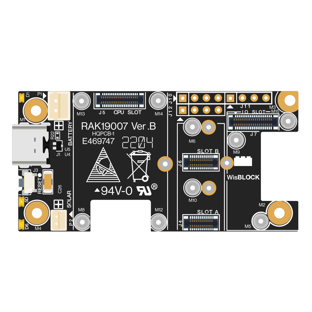
The RAK19007 WisBlock Base Board 2nd Gen is a modular and flexible base board designed by RAKwireless to facilitate the development of IoT (Internet of Things) projects. It serves as the foundation for the WisBlock system, which allows for the easy integration of various modules such as processors, sensors, and communication modules. The base board is particularly useful for rapid prototyping, as it simplifies the process of building complex IoT solutions.

Explore Projects Built with RAK19007 WisBlock Base Board 2nd Gen

Use Cirkit Designer to design, explore, and prototype these projects online. Some projects support real-time simulation. Click "Open Project" to start designing instantly!
MakerEdu Creator with Bluetooth, IR Sensors, LCD Display, and Push Button Interaction
Image of MKL Distance Measurement: A project utilizing  RAK19007 WisBlock Base Board 2nd Gen in a practical application
This circuit features a MakerEdu Creator microcontroller board interfaced with two MKE-S11 IR Infrared Obstacle Avoidance Sensors, a MKE-M02 Push Button Tact Switch, a MKE-M15 Bluetooth module, and a MKE-M08 LCD2004 I2C display module. The push button is connected to a digital input for user interaction, while the IR sensors are likely used for detecting obstacles. The Bluetooth module enables wireless communication, and the LCD display provides a user interface for displaying information or statuses.
Cirkit Designer LogoOpen Project in Cirkit Designer
Arduino UNO-Based Dual Stepper Motor Controller with Gesture Sensing and RTC Display
Image of Arduino UNO-Based Dual Stepper Motor Controller with Gesture Sensing and RTC Display: A project utilizing  RAK19007 WisBlock Base Board 2nd Gen in a practical application
This circuit is an Arduino UNO-based dual stepper motor controller that uses ULN2003A driver boards to control two 28BYJ-48 stepper motors. It features an APDS-9960 RGB and gesture sensor for gesture-based control, a DS1307 RTC module to display time on a 16x2 I2C LCD, and includes a green LED and two pushbuttons for additional control and status indication.
Cirkit Designer LogoOpen Project in Cirkit Designer
ESP8266 NodeMCU with LoRa and RS-485 Communication and Ethernet Connectivity
Image of Wiring Diagram LoRa: A project utilizing  RAK19007 WisBlock Base Board 2nd Gen in a practical application
This circuit serves as a multi-protocol communication hub featuring two ESP8266 NodeMCUs for processing, each connected to a LoRa Ra-02 SX1278 for long-range wireless communication. One NodeMCU is also connected to an RS-485 module for serial communication and a W5500 Ethernet module for network connectivity, with MB102 modules supplying power.
Cirkit Designer LogoOpen Project in Cirkit Designer
Arduino Nano and LoRa SX1278 Battery-Powered Wireless Display
Image of transreciver: A project utilizing  RAK19007 WisBlock Base Board 2nd Gen in a practical application
This circuit is a LoRa-based wireless communication system using an Arduino Nano to receive data packets and display them on an LCD. It includes a LoRa Ra-02 SX1278 module for long-range communication, a 3.7V battery with a charger module for power, and an LED indicator controlled by the Arduino.
Cirkit Designer LogoOpen Project in Cirkit Designer

Explore Projects Built with RAK19007 WisBlock Base Board 2nd Gen

Use Cirkit Designer to design, explore, and prototype these projects online. Some projects support real-time simulation. Click "Open Project" to start designing instantly!
Image of MKL Distance Measurement: A project utilizing  RAK19007 WisBlock Base Board 2nd Gen in a practical application
MakerEdu Creator with Bluetooth, IR Sensors, LCD Display, and Push Button Interaction
This circuit features a MakerEdu Creator microcontroller board interfaced with two MKE-S11 IR Infrared Obstacle Avoidance Sensors, a MKE-M02 Push Button Tact Switch, a MKE-M15 Bluetooth module, and a MKE-M08 LCD2004 I2C display module. The push button is connected to a digital input for user interaction, while the IR sensors are likely used for detecting obstacles. The Bluetooth module enables wireless communication, and the LCD display provides a user interface for displaying information or statuses.
Cirkit Designer LogoOpen Project in Cirkit Designer
Image of Arduino UNO-Based Dual Stepper Motor Controller with Gesture Sensing and RTC Display: A project utilizing  RAK19007 WisBlock Base Board 2nd Gen in a practical application
Arduino UNO-Based Dual Stepper Motor Controller with Gesture Sensing and RTC Display
This circuit is an Arduino UNO-based dual stepper motor controller that uses ULN2003A driver boards to control two 28BYJ-48 stepper motors. It features an APDS-9960 RGB and gesture sensor for gesture-based control, a DS1307 RTC module to display time on a 16x2 I2C LCD, and includes a green LED and two pushbuttons for additional control and status indication.
Cirkit Designer LogoOpen Project in Cirkit Designer
Image of Wiring Diagram LoRa: A project utilizing  RAK19007 WisBlock Base Board 2nd Gen in a practical application
ESP8266 NodeMCU with LoRa and RS-485 Communication and Ethernet Connectivity
This circuit serves as a multi-protocol communication hub featuring two ESP8266 NodeMCUs for processing, each connected to a LoRa Ra-02 SX1278 for long-range wireless communication. One NodeMCU is also connected to an RS-485 module for serial communication and a W5500 Ethernet module for network connectivity, with MB102 modules supplying power.
Cirkit Designer LogoOpen Project in Cirkit Designer
Image of transreciver: A project utilizing  RAK19007 WisBlock Base Board 2nd Gen in a practical application
Arduino Nano and LoRa SX1278 Battery-Powered Wireless Display
This circuit is a LoRa-based wireless communication system using an Arduino Nano to receive data packets and display them on an LCD. It includes a LoRa Ra-02 SX1278 module for long-range communication, a 3.7V battery with a charger module for power, and an LED indicator controlled by the Arduino.
Cirkit Designer LogoOpen Project in Cirkit Designer

Common Applications and Use Cases

  • Environmental monitoring (temperature, humidity, air quality)
  • Smart agriculture (soil moisture, weather stations)
  • Asset tracking and logistics
  • Wearable devices and health monitoring
  • Industrial automation and control systems
  • Smart city infrastructure

Technical Specifications

Key Technical Details

  • Operating Voltage: 3.3V
  • Maximum Input Voltage: 5.5V
  • IO Ports: Compatible with WisBlock IO modules
  • Connectivity: Supports WisBlock Core and WisBlock Sensor modules
  • Dimensions: 60mm x 31mm

Pin Configuration and Descriptions

Pin Number Description Notes
1 GND Ground
2 3V3 3.3V power supply
3 5V 5V power supply (USB or battery)
4-7 IO1 - IO4 General purpose IO pins
8-11 A1 - A4 Analog input pins
12 I2C SDA I2C Data line
13 I2C SCL I2C Clock line
14 UART TX UART Transmit
15 UART RX UART Receive
16 SPI MOSI SPI Data Out (Master Out)
17 SPI MISO SPI Data In (Master In)
18 SPI SCK SPI Clock
19 SPI NSS SPI Chip Select

Usage Instructions

How to Use the Component in a Circuit

  1. Powering the Board:

    • Ensure that the power supply does not exceed the maximum input voltage.
    • You can power the board through the USB connection or an external battery.
  2. Connecting WisBlock Modules:

    • Align the connectors of the WisBlock Core, Sensor, or IO modules with the corresponding connectors on the base board.
    • Gently press down to secure the modules in place.
  3. Programming the Board:

    • Connect the board to a computer using a USB cable.
    • Use the RAKwireless Arduino BSP or the RAKwireless nRF52 SDK for programming.
  4. Interfacing with External Components:

    • Utilize the IO pins for connecting external sensors, actuators, or other peripherals.
    • Ensure that the connected components are compatible with the logic level of the base board.

Important Considerations and Best Practices

  • Always disconnect the power before adding or removing modules.
  • Observe proper electrostatic discharge (ESD) precautions to avoid damaging the components.
  • When designing custom modules, ensure they follow the WisBlock interface standard for compatibility.
  • Avoid placing the board in environments with extreme temperatures, humidity, or electromagnetic interference.

Troubleshooting and FAQs

Common Issues

  • Module Not Recognized: Ensure that the module is properly seated and the pins are aligned correctly.
  • Power Issues: Verify that the power supply is within the specified range and the board is receiving power.
  • Communication Errors: Check the connections and settings for I2C, SPI, or UART interfaces.

Solutions and Tips for Troubleshooting

  • Re-seat any modules that are not recognized to ensure a good connection.
  • Use a multimeter to check the power supply voltage and board power rails.
  • For communication issues, use a logic analyzer to trace signals and verify protocol integrity.

FAQs

  • Q: Can I use any WisBlock module with this base board?

    • A: Yes, the RAK19007 is designed to be compatible with all WisBlock modules.
  • Q: How do I update the firmware on the base board?

    • A: Firmware updates are typically done through the WisBlock Core module using the appropriate SDK or Arduino BSP.
  • Q: What is the maximum number of modules I can attach to the base board?

    • A: The maximum number depends on the power consumption and IO requirements of the modules. Refer to the technical specifications of each module.

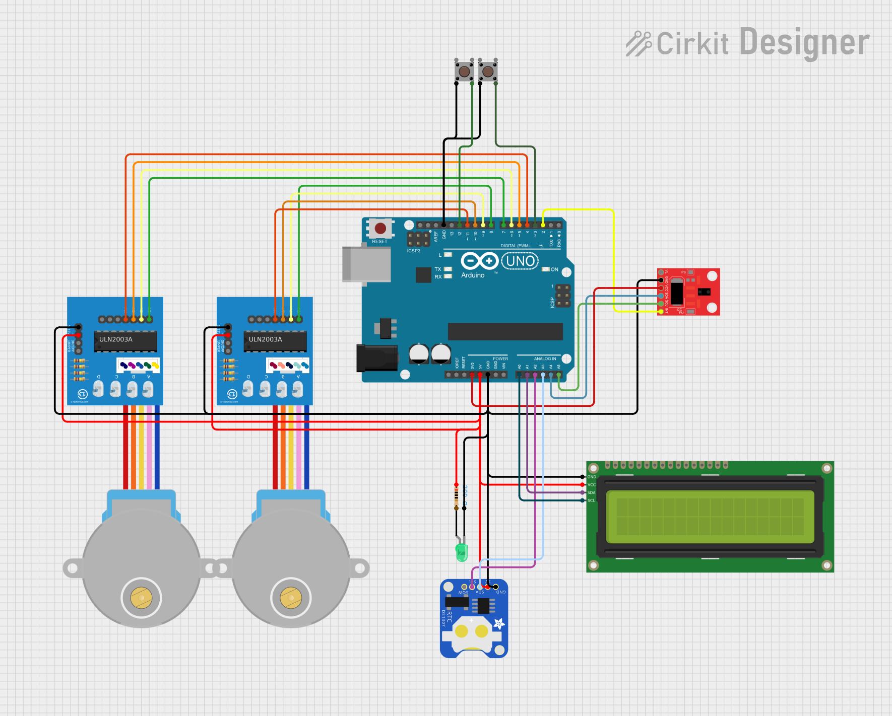
Example Code for Arduino UNO

// Example code for interfacing RAK19007 with Arduino UNO
// This example assumes the use of a compatible WisBlock Core module programmed via Arduino IDE.

#include <Wire.h>

void setup() {
  // Initialize serial communication
  Serial.begin(115200);
  
  // Initialize I2C communication
  Wire.begin();
  
  // Setup code for the specific WisBlock modules goes here
}

void loop() {
  // Main code to interact with the WisBlock modules goes here
  
  // Example: Reading data from a WisBlock sensor module
  // byte sensorData = readSensorData();
  // Serial.println(sensorData);
  
  // Delay between reads for stability
  delay(1000);
}

// Function to read data from a hypothetical sensor module
byte readSensorData() {
  // Replace with actual sensor read code
  return 0;
}

Note: The above code is a generic template and should be modified to fit the specific WisBlock Core and Sensor modules used in your project. Always refer to the module datasheets and example codes provided by RAKwireless for accurate programming details.