
How to Use ZS-042 RTC Module: Examples, Pinouts, and Specs
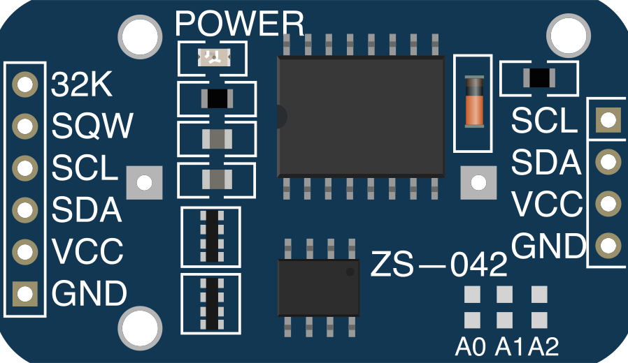
 Design with ZS-042 RTC Module in Cirkit Designer
Introduction
The ZS-042 RTC Module is a real-time clock (RTC) module designed to keep track of the current time and date. It is built around the DS3231 chip, a highly accurate RTC with an integrated temperature-compensated crystal oscillator. The module communicates with microcontrollers via the I2C interface, making it easy to integrate into a variety of projects. Additionally, it features a battery backup, ensuring that the timekeeping functionality continues even when the main power supply is disconnected.
Explore Projects Built with ZS-042 RTC Module
 Open Project in Cirkit Designer
 Open Project in Cirkit Designer
 Open Project in Cirkit Designer
 Open Project in Cirkit Designer
Explore Projects Built with ZS-042 RTC Module
Open Project in Cirkit DesignerOpen Project in Cirkit DesignerOpen Project in Cirkit DesignerOpen Project in Cirkit DesignerCommon Applications and Use Cases
- Time-stamping data in data logging systems
- Scheduling tasks in automation systems
- Building clocks and timers
- Maintaining time in IoT devices
- Calendar-based applications
Technical Specifications
Key Technical Details
- Chipset: DS3231 (temperature-compensated RTC)
- Communication Protocol: I2C (Inter-Integrated Circuit)
- Operating Voltage: 3.3V to 5V
- Backup Battery: CR2032 coin cell (not included)
- Accuracy: ±2 ppm from 0°C to +40°C, ±3.5 ppm from -40°C to +85°C
- Temperature Sensor: Built-in, with ±3°C accuracy
- Memory: 32 bytes of non-volatile RAM
- Dimensions: 38mm x 22mm x 14mm
Pin Configuration and Descriptions
The ZS-042 RTC Module has a 4-pin header for I2C communication. The pinout is as follows:
| Pin | Name | Description |
|---|---|---|
| 1 | VCC | Power supply input (3.3V or 5V) |
| 2 | GND | Ground |
| 3 | SDA | Serial Data Line for I2C communication |
| 4 | SCL | Serial Clock Line for I2C communication |
Usage Instructions
How to Use the ZS-042 RTC Module in a Circuit
- Power the Module: Connect the VCC pin to a 3.3V or 5V power source and the GND pin to ground.
- Connect to a Microcontroller: Use the SDA and SCL pins to connect the module to the corresponding I2C pins on your microcontroller. For example, on an Arduino UNO:
- SDA connects to A4
- SCL connects to A5
- Install a Backup Battery: Insert a CR2032 coin cell battery into the battery holder to enable timekeeping during power loss.
- Load the Required Library: Use the
RTCliblibrary in Arduino IDE for easy communication with the module. - Write and Upload Code: Use the example code below to initialize the module and read the current time.
Example Code for Arduino UNO
#include <Wire.h>
#include <RTClib.h>

// Create an RTC object
RTC_DS3231 rtc;

void setup() {
  Serial.begin(9600); // Initialize serial communication at 9600 baud
  Wire.begin();       // Initialize I2C communication

  if (!rtc.begin()) {
    Serial.println("Couldn't find RTC module!");
    while (1); // Halt the program if the RTC is not detected
  }

  if (rtc.lostPower()) {
    Serial.println("RTC lost power, setting the time!");
    // Set the RTC to the current date and time
    rtc.adjust(DateTime(F(__DATE__), F(__TIME__)));
  }
}

void loop() {
  DateTime now = rtc.now(); // Get the current date and time

  // Print the current date and time to the Serial Monitor
  Serial.print(now.year(), DEC);
  Serial.print('/');
  Serial.print(now.month(), DEC);
  Serial.print('/');
  Serial.print(now.day(), DEC);
  Serial.print(" ");
  Serial.print(now.hour(), DEC);
  Serial.print(':');
  Serial.print(now.minute(), DEC);
  Serial.print(':');
  Serial.print(now.second(), DEC);
  Serial.println();

  delay(1000); // Wait for 1 second before updating
}
Important Considerations and Best Practices
- Ensure the backup battery is installed correctly to maintain timekeeping during power loss.
- Avoid shorting the battery terminals, as this can damage the module.
- Use pull-up resistors (typically 4.7kΩ) on the SDA and SCL lines if your microcontroller does not have internal pull-ups enabled.
- Keep I2C wires as short as possible to avoid communication issues caused by noise or interference.
Troubleshooting and FAQs
Common Issues and Solutions
RTC Module Not Detected
- Cause: Incorrect wiring or loose connections.
- Solution: Double-check the connections between the module and the microcontroller. Ensure SDA and SCL are connected to the correct pins.
Incorrect Time Displayed
- Cause: RTC lost power or was not initialized properly.
- Solution: Use the
rtc.adjust()function to set the correct time.
No Output on Serial Monitor
- Cause: Serial communication not initialized or incorrect baud rate.
- Solution: Ensure
Serial.begin(9600)is called in thesetup()function and the Serial Monitor is set to 9600 baud.
Battery Backup Not Working
- Cause: Dead or improperly installed battery.
- Solution: Replace the CR2032 battery and ensure it is installed with the correct polarity.
FAQs
Q: Can the ZS-042 RTC Module work with 3.3V microcontrollers?
A: Yes, the module is compatible with both 3.3V and 5V systems.Q: How long does the backup battery last?
A: A typical CR2032 battery can last several years, depending on usage and environmental conditions.Q: Can I use the module without a backup battery?
A: Yes, but the time will reset whenever the main power is disconnected.Q: Does the module support alarms?
A: Yes, the DS3231 chip supports alarms, but additional programming is required to use this feature.
This concludes the documentation for the ZS-042 RTC Module.