How to Use Arduino Nano Atmega 328P Nano: Examples, Pinouts, and Specs
Introduction
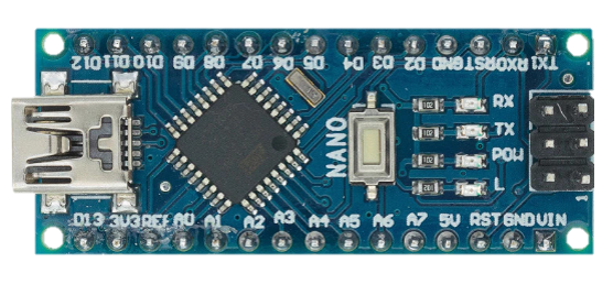
The Arduino Nano is a compact microcontroller board developed by Arduino, based on the ATmega328P microcontroller. It is designed for easy integration into a wide range of projects, offering a small form factor ideal for space-constrained applications. The Nano features digital and analog input/output pins, USB connectivity for programming, and compatibility with the Arduino IDE, making it a versatile choice for both beginners and experienced developers.
Explore Projects Built with Arduino Nano Atmega 328P Nano

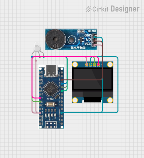

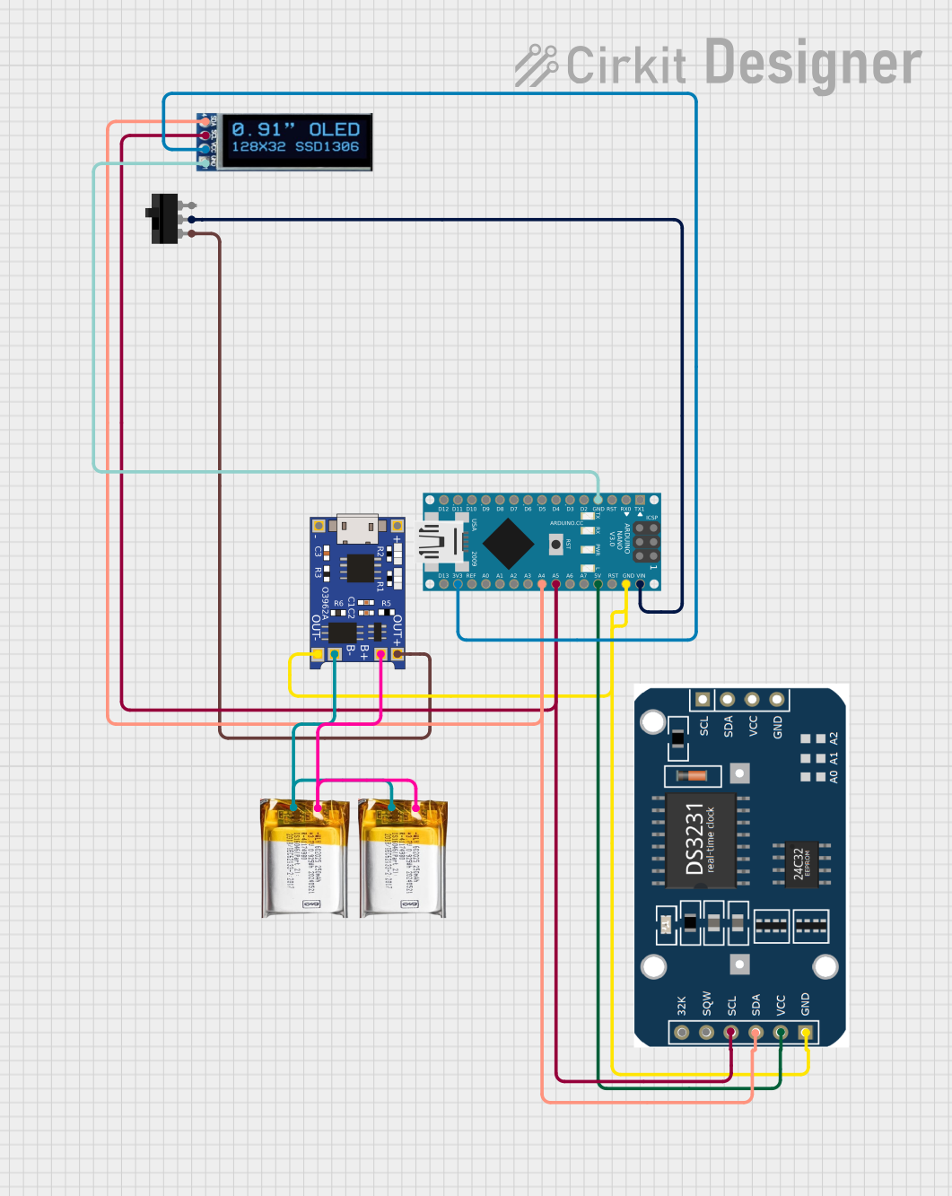
Explore Projects Built with Arduino Nano Atmega 328P Nano
Common Applications and Use Cases
- Prototyping and development of embedded systems
- Robotics and automation projects
- IoT (Internet of Things) devices
- Wearable electronics
- Sensor data acquisition and processing
- Educational tools for learning microcontroller programming
Technical Specifications
The Arduino Nano is equipped with the following technical features:
| Specification | Details |
|---|---|
| Microcontroller | ATmega328P |
| Operating Voltage | 5V |
| Input Voltage (recommended) | 7-12V |
| Input Voltage (limit) | 6-20V |
| Digital I/O Pins | 14 (6 PWM outputs) |
| Analog Input Pins | 8 |
| DC Current per I/O Pin | 40 mA |
| Flash Memory | 32 KB (2 KB used by bootloader) |
| SRAM | 2 KB |
| EEPROM | 1 KB |
| Clock Speed | 16 MHz |
| USB Connectivity | Mini-B USB |
| Dimensions | 18 x 45 mm |
| Weight | 7 g |
Pin Configuration and Descriptions
The Arduino Nano has a total of 30 pins, including power, digital, and analog pins. Below is a detailed description of the pin configuration:
Power Pins
| Pin | Name | Description |
|---|---|---|
| 1 | VIN | Input voltage to the board when using an external power source (7-12V recommended). |
| 2 | GND | Ground pins (multiple GND pins available). |
| 3 | 5V | Regulated 5V output from the onboard regulator. |
| 4 | 3.3V | Regulated 3.3V output (limited to 50 mA). |
| 5 | AREF | Reference voltage for analog inputs. |
| 6 | RESET | Resets the microcontroller when pulled LOW. |
Digital Pins
| Pin | Name | Description |
|---|---|---|
| D0-D13 | Digital I/O | General-purpose digital input/output pins. Pins D3, D5, D6, D9, D10, and D11 support PWM. |
Analog Pins
| Pin | Name | Description |
|---|---|---|
| A0-A7 | Analog Input | Used for reading analog signals (0-5V). Can also be used as digital I/O pins. |
Communication Pins
| Pin | Name | Description |
|---|---|---|
| D0, D1 | RX, TX | Used for serial communication. |
| D10 | SS | SPI Slave Select pin. |
| D11 | MOSI | SPI Master Out Slave In pin. |
| D12 | MISO | SPI Master In Slave Out pin. |
| D13 | SCK | SPI Clock pin. |
Usage Instructions
How to Use the Arduino Nano in a Circuit
Powering the Board:
- Connect the Nano to your computer via a Mini-B USB cable for programming and power.
- Alternatively, supply power through the VIN pin (7-12V recommended) or the 5V pin (regulated 5V).
Programming the Board:
- Install the Arduino IDE on your computer.
- Select "Arduino Nano" as the board type and "ATmega328P" as the processor in the Tools menu.
- Connect the Nano to your computer and upload your code via the USB cable.
Connecting Components:
- Use the digital pins (D0-D13) for digital input/output operations.
- Use the analog pins (A0-A7) for reading analog signals or as additional digital I/O pins.
- Connect sensors, actuators, and other peripherals as needed, ensuring current and voltage limits are not exceeded.
Important Considerations and Best Practices
- Avoid drawing more than 40 mA from any single I/O pin to prevent damage to the microcontroller.
- Use external pull-up or pull-down resistors for stable digital input signals.
- When using the analog pins, ensure the input voltage does not exceed 5V.
- For long-term projects, consider using a heat sink or fan if the board operates in high-temperature environments.
Example Code for Arduino Nano
The following example demonstrates how to blink an LED connected to pin D13:
// Blink an LED connected to pin D13
// This example toggles the LED on and off every second.

void setup() {
  pinMode(13, OUTPUT); // Set pin D13 as an output
}

void loop() {
  digitalWrite(13, HIGH); // Turn the LED on
  delay(1000);            // Wait for 1 second
  digitalWrite(13, LOW);  // Turn the LED off
  delay(1000);            // Wait for 1 second
}
Troubleshooting and FAQs
Common Issues and Solutions
The board is not detected by the computer:
- Ensure the USB cable is properly connected and functional.
- Install the correct USB drivers for the Arduino Nano.
Code upload fails:
- Verify that the correct board and processor are selected in the Arduino IDE.
- Check the COM port in the Tools menu and ensure it matches the connected device.
The board is not powering on:
- Confirm that the power source (USB or external) is supplying the correct voltage.
- Check for loose connections or damaged components.
Analog readings are unstable:
- Use a capacitor (e.g., 0.1 µF) between the analog input pin and GND to filter noise.
FAQs
Q: Can the Arduino Nano run on 3.3V?
A: The Nano operates at 5V, but it can accept 3.3V signals on its input pins. However, powering the board directly with 3.3V is not recommended.
Q: How do I reset the Arduino Nano?
A: Press the onboard reset button or connect the RESET pin to GND momentarily.
Q: Can I use the Arduino Nano for wireless communication?
A: Yes, you can connect wireless modules like Bluetooth (HC-05) or Wi-Fi (ESP8266) to the Nano via its serial or digital pins.
Q: What is the maximum current the Nano can supply?
A: The 5V pin can supply up to 500 mA when powered via USB, but this depends on the USB port's capacity.
By following this documentation, you can effectively integrate the Arduino Nano into your projects and troubleshoot common issues with ease.