How to Use SSR 4 channel: Examples, Pinouts, and Specs
Introduction
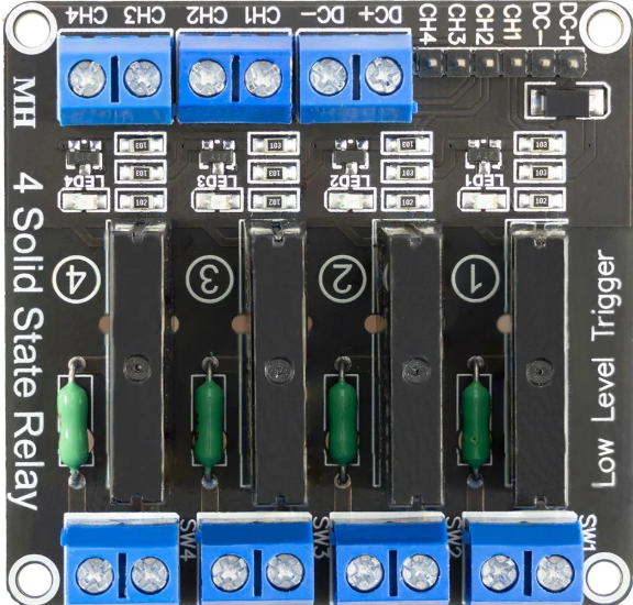
The SSR 4 Channel, manufactured by SSR (Part ID: SSR), is a Solid State Relay module designed for switching electrical loads without the use of moving parts. This design ensures faster response times, higher reliability, and longer operational life compared to traditional electromechanical relays. The module features four independent channels, making it ideal for controlling multiple loads simultaneously.
Explore Projects Built with SSR 4 channel
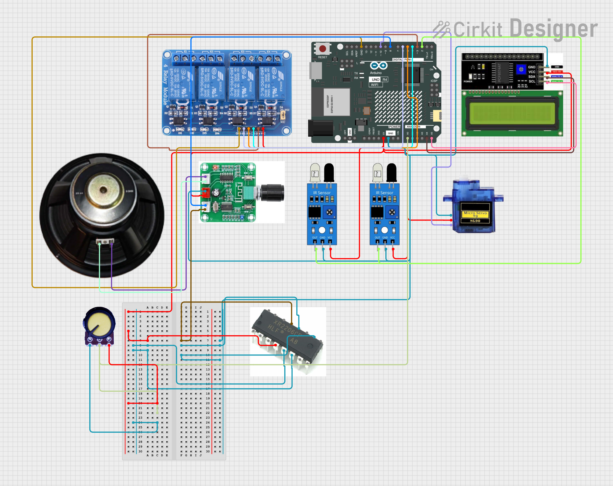
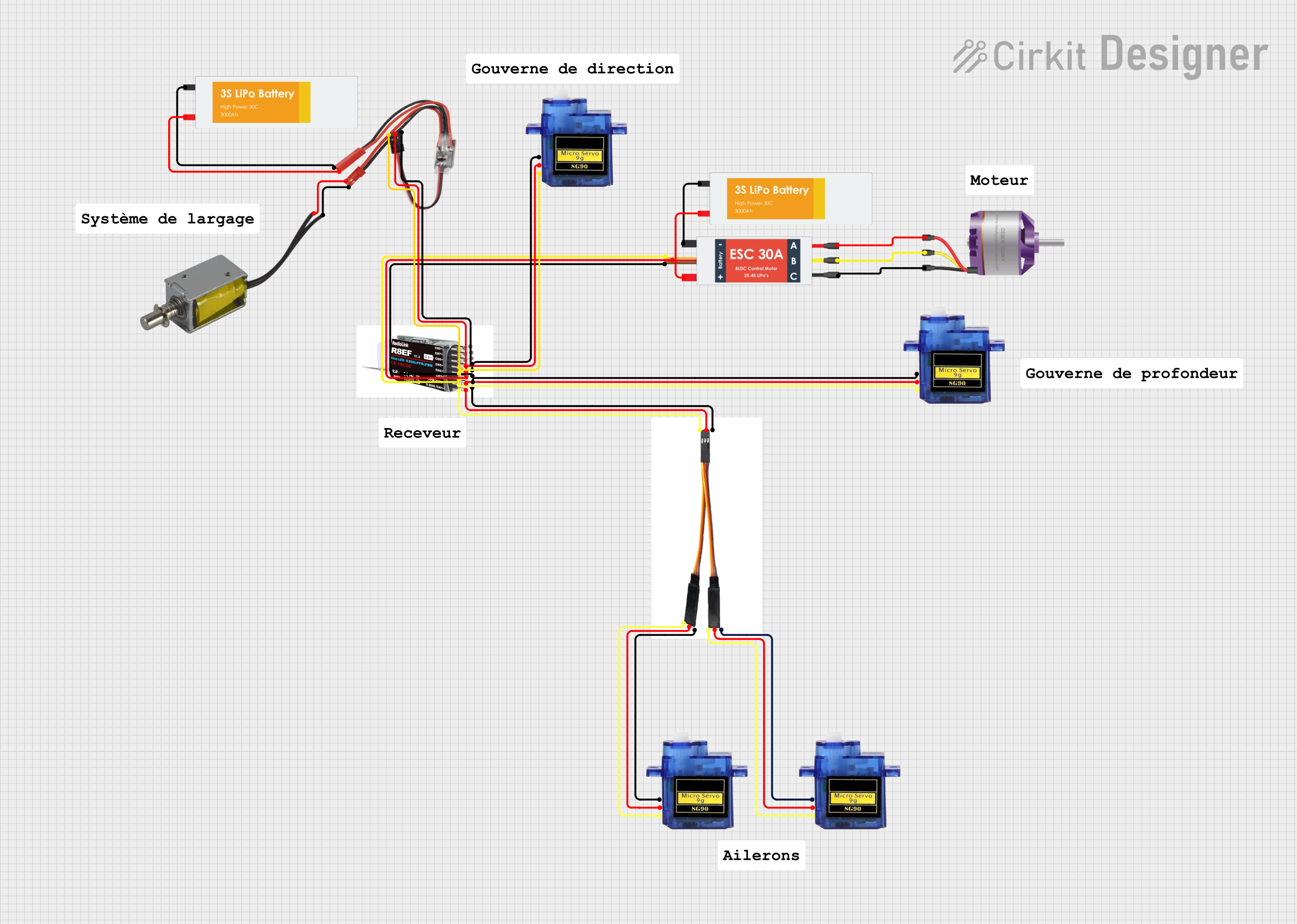


Explore Projects Built with SSR 4 channel
Common Applications and Use Cases
- Industrial automation systems
- Home automation (e.g., controlling lights, fans, or appliances)
- Motor control and heating element switching
- High-speed switching applications
- Projects requiring isolation between control and load circuits
Technical Specifications
The SSR 4 Channel module is designed to handle a variety of loads while maintaining electrical isolation between the control and load sides. Below are the key technical details:
General Specifications
| Parameter | Value |
|---|---|
| Manufacturer | SSR |
| Part ID | SSR |
| Number of Channels | 4 |
| Control Voltage | 3.3V to 5V DC |
| Load Voltage Range | 24V to 380V AC |
| Load Current (per channel) | Up to 2A |
| Isolation Voltage | ≥ 2500V AC |
| Response Time | ≤ 10 ms |
| Operating Temperature | -30°C to 80°C |
| Dimensions | 60mm x 90mm x 20mm |
Pin Configuration and Descriptions
The SSR 4 Channel module has a straightforward pinout for easy integration into circuits. Below is the pin configuration:
Control Side (Input)
| Pin Name | Description |
|---|---|
| IN1 | Control signal for Channel 1 (3.3V to 5V DC) |
| IN2 | Control signal for Channel 2 (3.3V to 5V DC) |
| IN3 | Control signal for Channel 3 (3.3V to 5V DC) |
| IN4 | Control signal for Channel 4 (3.3V to 5V DC) |
| GND | Ground (common for all control signals) |
| VCC | Power supply for the control circuit (5V DC) |
Load Side (Output)
| Terminal Name | Description |
|---|---|
| CH1+ / CH1- | Load terminals for Channel 1 |
| CH2+ / CH2- | Load terminals for Channel 2 |
| CH3+ / CH3- | Load terminals for Channel 3 |
| CH4+ / CH4- | Load terminals for Channel 4 |
Usage Instructions
How to Use the SSR 4 Channel in a Circuit
- Power the Control Circuit: Connect the VCC pin to a 5V DC power source and the GND pin to the ground of your control circuit.
- Connect Control Signals: Use digital output pins from a microcontroller (e.g., Arduino UNO) to send control signals to the IN1, IN2, IN3, and IN4 pins. A HIGH signal (3.3V or 5V) will activate the corresponding relay channel.
- Connect the Load: Attach the load to the CHx+ and CHx- terminals of the desired channel(s). Ensure the load voltage and current are within the specified range.
- Isolation: The SSR module provides electrical isolation between the control and load sides, ensuring safety and protecting the control circuit from high voltages.
Important Considerations and Best Practices
- Heat Dissipation: Ensure proper ventilation or heat sinking if the module is used to switch high-power loads continuously.
- Load Ratings: Do not exceed the maximum load current (2A per channel) or voltage (380V AC).
- Control Signal Voltage: Use a control signal voltage within the specified range (3.3V to 5V DC) to avoid damage to the module.
- Inductive Loads: When switching inductive loads (e.g., motors), use appropriate snubber circuits or varistors to suppress voltage spikes.
Example: Using the SSR 4 Channel with Arduino UNO
Below is an example of how to control the SSR 4 Channel module using an Arduino UNO:
// Example: Controlling SSR 4 Channel with Arduino UNO
// This code toggles all four channels ON and OFF with a 1-second delay.

#define CH1 2  // Pin 2 connected to IN1
#define CH2 3  // Pin 3 connected to IN2
#define CH3 4  // Pin 4 connected to IN3
#define CH4 5  // Pin 5 connected to IN4

void setup() {
  // Set control pins as OUTPUT
  pinMode(CH1, OUTPUT);
  pinMode(CH2, OUTPUT);
  pinMode(CH3, OUTPUT);
  pinMode(CH4, OUTPUT);
}

void loop() {
  // Turn all channels ON
  digitalWrite(CH1, HIGH); // Activate Channel 1
  digitalWrite(CH2, HIGH); // Activate Channel 2
  digitalWrite(CH3, HIGH); // Activate Channel 3
  digitalWrite(CH4, HIGH); // Activate Channel 4
  delay(1000);             // Wait for 1 second

  // Turn all channels OFF
  digitalWrite(CH1, LOW);  // Deactivate Channel 1
  digitalWrite(CH2, LOW);  // Deactivate Channel 2
  digitalWrite(CH3, LOW);  // Deactivate Channel 3
  digitalWrite(CH4, LOW);  // Deactivate Channel 4
  delay(1000);             // Wait for 1 second
}
Troubleshooting and FAQs
Common Issues and Solutions
SSR Channels Not Switching
- Cause: Insufficient control signal voltage.
- Solution: Ensure the control signal voltage is within the range of 3.3V to 5V DC.
Load Not Turning ON
- Cause: Incorrect wiring of the load terminals.
- Solution: Verify the load is connected to the correct CHx+ and CHx- terminals.
Overheating
- Cause: Exceeding the maximum load current or poor ventilation.
- Solution: Reduce the load current or improve heat dissipation with a heat sink or fan.
Interference with Microcontroller
- Cause: Ground loop or noise from the load side.
- Solution: Use optocouplers or ensure proper grounding and isolation.
FAQs
Q1: Can the SSR 4 Channel switch DC loads?
A1: No, this module is designed for AC loads only. For DC loads, use a DC-specific SSR module.
Q2: Can I control the SSR 4 Channel with a 3.3V microcontroller?
A2: Yes, the module supports control signals as low as 3.3V DC.
Q3: What happens if I exceed the load current rating?
A3: Exceeding the load current rating may damage the SSR module. Always ensure the load is within the specified limits.
Q4: Is the SSR 4 Channel module safe to use with high voltages?
A4: Yes, the module provides electrical isolation between the control and load sides, ensuring safety when used correctly. Always follow proper safety precautions when working with high voltages.