How to Use écran Arduino Giga Dispaly Shield: Examples, Pinouts, and Specs
Introduction
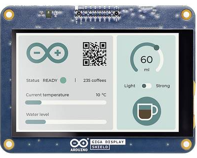
The Arduino Giga Display Shield is a versatile display module designed specifically for use with Arduino Giga boards. It features a large, high-resolution screen that enables users to create visually rich interfaces and display real-time data. This shield is ideal for projects requiring graphical user interfaces, data visualization, or interactive displays. Its plug-and-play design ensures seamless integration with Arduino Giga boards, making it a perfect choice for both beginners and advanced users.
Explore Projects Built with écran Arduino Giga Dispaly Shield

Explore Projects Built with écran Arduino Giga Dispaly Shield
Common Applications and Use Cases
- Graphical user interfaces for embedded systems
- Real-time data visualization (e.g., sensor readings, graphs)
- Interactive projects with touch input (if supported)
- Educational tools and prototypes
- IoT dashboards and monitoring systems
Technical Specifications
Below are the key technical details of the Arduino Giga Display Shield:
| Specification | Details |
|---|---|
| Manufacturer | Arduino |
| Manufacturer Part ID | Uno |
| Display Type | TFT LCD |
| Screen Size | 3.5 inches |
| Resolution | 480 x 320 pixels |
| Interface | SPI (Serial Peripheral Interface) |
| Operating Voltage | 3.3V |
| Backlight Control | PWM (Pulse Width Modulation) |
| Touchscreen Support | Yes (Resistive or Capacitive, model-dependent) |
| Dimensions | 85mm x 55mm x 20mm |
Pin Configuration and Descriptions
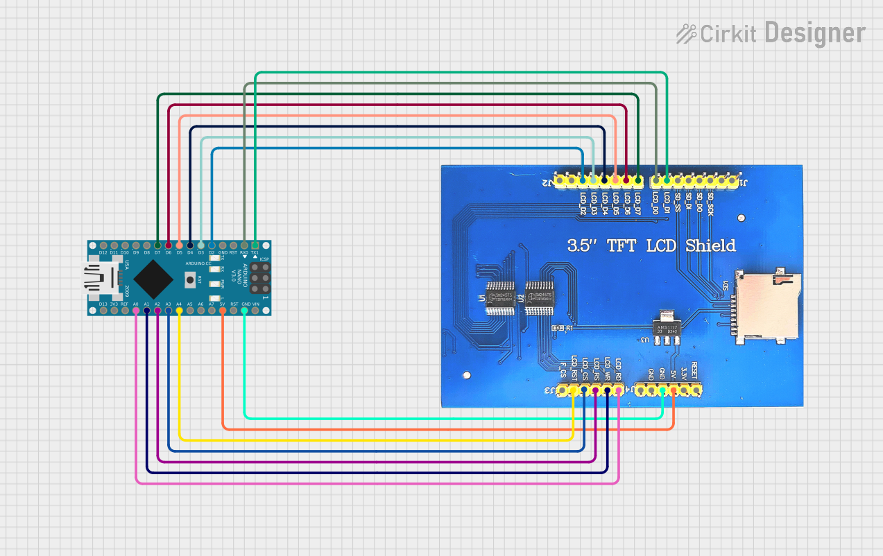
The Arduino Giga Display Shield connects directly to the Arduino Giga board via its headers. Below is the pin configuration:
| Pin Name | Function | Description |
|---|---|---|
| GND | Ground | Common ground for the shield and Arduino board. |
| VCC | Power Supply | Provides 3.3V power to the display. |
| CS | Chip Select | Selects the display for SPI communication. |
| SCK | Serial Clock | SPI clock signal for data synchronization. |
| MOSI | Master Out Slave In | SPI data line for sending data to the display. |
| MISO | Master In Slave Out | SPI data line for receiving data from the display. |
| RESET | Reset | Resets the display module. |
| DC | Data/Command Control | Switches between data and command modes. |
| BL | Backlight Control | Controls the brightness of the display. |
| T_IRQ | Touchscreen Interrupt (Optional) | Detects touch events (if touchscreen is supported). |
Usage Instructions
How to Use the Component in a Circuit
- Connect the Shield to the Arduino Giga Board: Align the shield's pins with the Arduino Giga board's headers and press gently to ensure a secure connection.
- Power the System: Connect the Arduino Giga board to a power source (e.g., USB or external power supply).
- Install Required Libraries: Install the necessary libraries for the display, such as
Adafruit_GFXandAdafruit_TFTLCD, via the Arduino IDE Library Manager. - Write and Upload Code: Use the Arduino IDE to write and upload code to control the display.
Important Considerations and Best Practices
- Ensure the shield is properly aligned with the Arduino Giga board to avoid damaging the pins.
- Use a stable power source to prevent flickering or display issues.
- If using the touchscreen feature, ensure the appropriate library is installed and configured.
- Avoid exposing the display to direct sunlight or extreme temperatures to prevent damage.
Example Code for Arduino UNO
Below is an example code snippet to display text on the Arduino Giga Display Shield:
#include <Adafruit_GFX.h>      // Graphics library for the display
#include <Adafruit_TFTLCD.h>  // Library for the TFT LCD display

#define LCD_CS A3  // Chip Select pin
#define LCD_CD A2  // Command/Data pin
#define LCD_WR A1  // LCD Write pin
#define LCD_RD A0  // LCD Read pin
#define LCD_RESET A4  // Reset pin

// Initialize the display object
Adafruit_TFTLCD tft(LCD_CS, LCD_CD, LCD_WR, LCD_RD, LCD_RESET);

void setup() {
  tft.begin();  // Initialize the display
  tft.setRotation(1);  // Set display orientation
  tft.fillScreen(0x0000);  // Clear the screen (black background)

  // Display text
  tft.setTextColor(0xFFFF);  // Set text color to white
  tft.setTextSize(2);        // Set text size
  tft.setCursor(10, 10);     // Set cursor position
  tft.print("Hello, Arduino!");  // Print text to the display
}

void loop() {
  // No actions in the loop for this example
}
Notes:
- Replace pin definitions with the actual pin numbers for your specific shield model if they differ.
- Adjust the
setRotation()parameter to change the screen orientation.
Troubleshooting and FAQs
Common Issues and Solutions
The display does not turn on:
- Ensure the shield is properly connected to the Arduino Giga board.
- Verify that the Arduino board is powered and the correct voltage is supplied.
- Check for loose or damaged pins.
The screen is blank or flickering:
- Confirm that the required libraries are installed and included in your code.
- Ensure the SPI connections (e.g., CS, SCK, MOSI) are correctly defined in the code.
- Use a stable power source to avoid voltage fluctuations.
Touchscreen is unresponsive:
- Verify that the touchscreen library is installed and configured.
- Check the T_IRQ pin connection and ensure it is properly defined in the code.
- Calibrate the touchscreen if necessary.
Text or graphics appear distorted:
- Ensure the correct screen resolution and orientation are set in the code.
- Verify that the display initialization code matches the shield's specifications.
FAQs
Q: Can I use this shield with other Arduino boards?
A: The Arduino Giga Display Shield is designed for Arduino Giga boards. While it may work with other boards, compatibility is not guaranteed and may require additional wiring or modifications.
Q: Does the shield support touch input?
A: Yes, the shield supports touch input if the model includes a touchscreen. Ensure the appropriate library is installed and configured.
Q: How do I control the backlight brightness?
A: The backlight can be controlled using the BL pin with a PWM signal. Adjust the duty cycle to change the brightness.
Q: Can I use this shield for video playback?
A: The shield is not optimized for video playback due to the limitations of the SPI interface and Arduino's processing power. It is best suited for static or dynamic graphical content.