Cirkit Designer Logo
Cirkit Designer
Your all-in-one circuit design IDE
Home / 
Component Documentation

How to Use Step down Module: Examples, Pinouts, and Specs

Image of Step down Module
Cirkit Designer LogoDesign with Step down Module in Cirkit Designer

Introduction

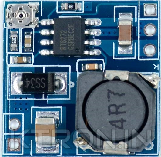
The Nuke Smoll step-down module is a compact and efficient voltage regulator designed to convert a higher input voltage to a lower, regulated output voltage. This electronic component is essential in applications where the operating voltage of certain electronic devices is lower than the available power supply voltage. Common applications include battery-powered systems, power supply design, and embedded systems where a stable and lower voltage is required.

Explore Projects Built with Step down Module

Use Cirkit Designer to design, explore, and prototype these projects online. Some projects support real-time simulation. Click "Open Project" to start designing instantly!
Battery-Powered UPS with Step-Down Buck Converter and BMS
Image of Mini ups: A project utilizing Step down Module in a practical application
This circuit is a power management system that steps down a 240V AC input to a lower DC voltage using a buck converter, which then powers a 40W UPS. The UPS is controlled by a rocker switch and is backed up by a battery management system (BMS) connected to three 3.7V batteries in series, ensuring continuous power supply.
Cirkit Designer LogoOpen Project in Cirkit Designer
Battery-Powered DC-DC Converter System for Multi-Voltage Power Distribution
Image of test 1 ih: A project utilizing Step down Module in a practical application
This circuit converts a 38.5V battery output to multiple lower voltage levels using a series of DC-DC converters and a power module. It includes an emergency stop switch for safety and distributes power to various components such as a relay module, USB ports, and a bus servo adaptor.
Cirkit Designer LogoOpen Project in Cirkit Designer
DC-DC Converter and Relay Module Power Distribution System
Image of relay: A project utilizing Step down Module in a practical application
This circuit consists of a DC-DC converter powering a 6-channel power module, which in turn supplies 5V to a 2-relay module. The power module distributes the converted voltage to the relay module, enabling it to control external devices.
Cirkit Designer LogoOpen Project in Cirkit Designer
Voltage Regulation System with MT3608 Boost and LM2596 Buck Converters
Image of solar system router ups: A project utilizing Step down Module in a practical application
This circuit consists of two MT3608 boost converters and an LM2596 step-down module, each connected to separate 12V power supplies. The MT3608 modules are configured to step up the voltage from their respective power supplies, while the LM2596 module steps down the voltage from a 12V battery. Diodes are used to ensure correct current flow direction, potentially for protection or isolation between different parts of the circuit.
Cirkit Designer LogoOpen Project in Cirkit Designer

Explore Projects Built with Step down Module

Use Cirkit Designer to design, explore, and prototype these projects online. Some projects support real-time simulation. Click "Open Project" to start designing instantly!
Image of Mini ups: A project utilizing Step down Module in a practical application
Battery-Powered UPS with Step-Down Buck Converter and BMS
This circuit is a power management system that steps down a 240V AC input to a lower DC voltage using a buck converter, which then powers a 40W UPS. The UPS is controlled by a rocker switch and is backed up by a battery management system (BMS) connected to three 3.7V batteries in series, ensuring continuous power supply.
Cirkit Designer LogoOpen Project in Cirkit Designer
Image of test 1 ih: A project utilizing Step down Module in a practical application
Battery-Powered DC-DC Converter System for Multi-Voltage Power Distribution
This circuit converts a 38.5V battery output to multiple lower voltage levels using a series of DC-DC converters and a power module. It includes an emergency stop switch for safety and distributes power to various components such as a relay module, USB ports, and a bus servo adaptor.
Cirkit Designer LogoOpen Project in Cirkit Designer
Image of relay: A project utilizing Step down Module in a practical application
DC-DC Converter and Relay Module Power Distribution System
This circuit consists of a DC-DC converter powering a 6-channel power module, which in turn supplies 5V to a 2-relay module. The power module distributes the converted voltage to the relay module, enabling it to control external devices.
Cirkit Designer LogoOpen Project in Cirkit Designer
Image of solar system router ups: A project utilizing Step down Module in a practical application
Voltage Regulation System with MT3608 Boost and LM2596 Buck Converters
This circuit consists of two MT3608 boost converters and an LM2596 step-down module, each connected to separate 12V power supplies. The MT3608 modules are configured to step up the voltage from their respective power supplies, while the LM2596 module steps down the voltage from a 12V battery. Diodes are used to ensure correct current flow direction, potentially for protection or isolation between different parts of the circuit.
Cirkit Designer LogoOpen Project in Cirkit Designer

Technical Specifications

Key Technical Details

  • Input Voltage Range: 6V to 32V
  • Output Voltage Range: 1.25V to 30V (adjustable)
  • Maximum Output Current: 3A (with proper heat sinking)
  • Conversion Efficiency: Up to 92%
  • Switching Frequency: 150kHz
  • Operating Temperature: -40°C to +85°C

Pin Configuration and Descriptions

Pin Number Name Description
1 VIN Input voltage (6V to 32V)
2 GND Ground reference for the module
3 VOUT Regulated output voltage (1.25V to 30V)
4 ADJ Adjustment pin for setting the output voltage
5 EN Enable pin for turning the module on/off

Usage Instructions

Integration into a Circuit

  1. Connecting Input Power:

    • Connect the positive terminal of your power source to the VIN pin.
    • Connect the negative terminal to the GND pin.
  2. Setting Output Voltage:

    • Adjust the onboard potentiometer to set the desired output voltage.
    • Use a multimeter to measure the output voltage while adjusting.
  3. Enabling the Module:

    • The EN pin can be left floating to keep the module always on.
    • Alternatively, connect the EN pin to a logic-level signal to turn the module on or off as needed.

Best Practices

  • Always ensure the input voltage does not exceed the specified maximum of 32V.
  • Do not exceed the maximum output current of 3A without adequate heat sinking.
  • Use capacitors at the input and output for better voltage regulation and to reduce noise.
  • When adjusting the output voltage, turn the potentiometer slowly and monitor the voltage to prevent overshooting the desired voltage.

Troubleshooting and FAQs

Common Issues

  • Output voltage is too high or too low:

    • Check the adjustment of the potentiometer and re-adjust as necessary.
    • Ensure that the input voltage is within the specified range.
  • Module is overheating:

    • Verify that the current draw is within the module's limits.
    • Improve heat dissipation with a heat sink or by reducing the load.
  • No output voltage:

    • Check connections to VIN and GND for proper soldering and contact.
    • Ensure the EN pin is either floating or receiving a high logic-level signal.

FAQs

Q: Can I use the Nuke Smoll step-down module to charge batteries? A: Yes, but you must ensure the output voltage and current are appropriate for the battery being charged.

Q: Is it possible to synchronize multiple Nuke Smoll modules? A: No, the Nuke Smoll does not support synchronization.

Q: How do I know if the module is operating within its efficiency range? A: Measure the input and output power and calculate the efficiency. The module operates most efficiently at 92% under optimal conditions.

Example Arduino UNO Connection

// Example code to control the Nuke Smoll step-down module with an Arduino UNO

const int enablePin = 7; // Connect to the EN pin of the module

void setup() {
  pinMode(enablePin, OUTPUT);
  digitalWrite(enablePin, LOW); // Start with the module turned off
}

void loop() {
  // Turn on the step-down module
  digitalWrite(enablePin, HIGH);
  delay(5000); // Keep the module on for 5 seconds

  // Turn off the step-down module
  digitalWrite(enablePin, LOW);
  delay(5000); // Keep the module off for 5 seconds
}

In this example, the Arduino UNO is used to turn the Nuke Smoll step-down module on and off with a 5-second interval. The EN pin of the module is controlled by the Arduino's digital pin 7. This simple code can be integrated into larger projects where voltage regulation is required intermittently.