Cirkit Designer Logo
Cirkit Designer
Your all-in-one circuit design IDE
Home / 
Component Documentation

How to Use 2P Breaker: Examples, Pinouts, and Specs
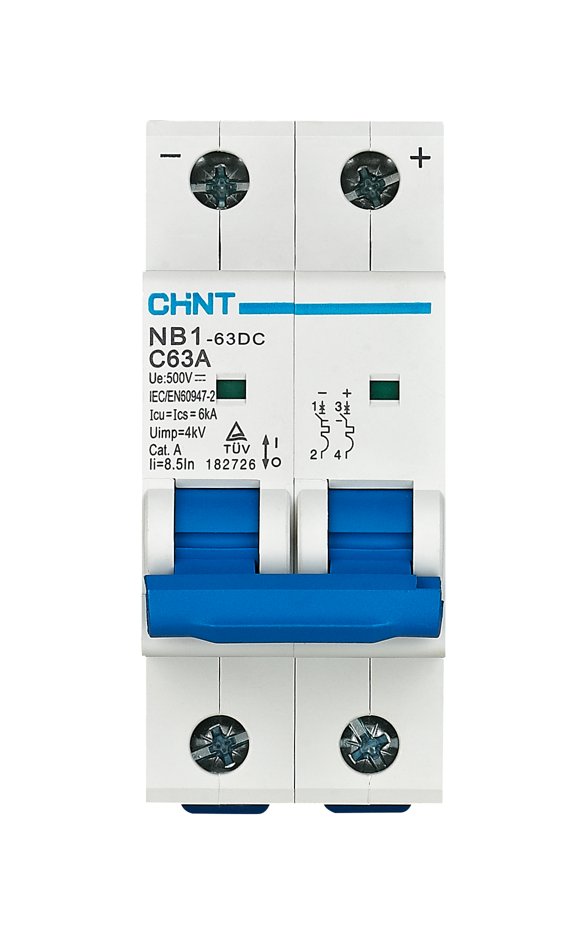

Image of 2P Breaker
Cirkit Designer LogoDesign with 2P Breaker in Cirkit Designer

Introduction

  • The 2P Breaker, or 2-pole circuit breaker, is an essential safety device designed to protect electrical circuits from overloads and short circuits. It is specifically engineered for dual-phase systems, where it can simultaneously disconnect power from both phases to ensure safety and prevent damage to connected equipment.
  • Common applications include residential and commercial electrical panels, industrial machinery, HVAC systems, and any dual-phase electrical setup requiring reliable circuit protection.

Explore Projects Built with 2P Breaker
Use Cirkit Designer to design, explore, and prototype these projects online. Some projects support real-time simulation. Click "Open Project" to start designing instantly!
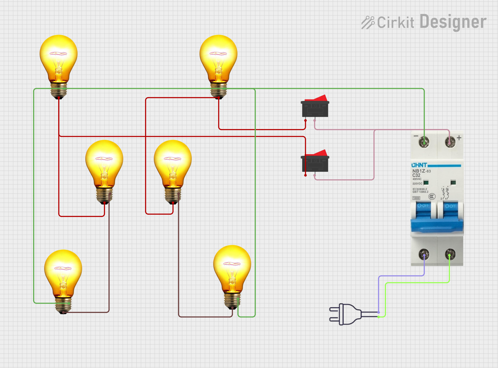
AC Bulb Control Circuit with Rocker Switches and Circuit Breaker
Image of schematic: A project utilizing 2P Breaker in a practical application
This circuit is designed to control multiple AC bulbs using two rocker switches and a circuit breaker for safety. The circuit is powered by a 220V AC source, with the circuit breaker providing protection and the rocker switches allowing selective control of the connected bulbs.
Cirkit Designer LogoOpen Project in Cirkit Designer
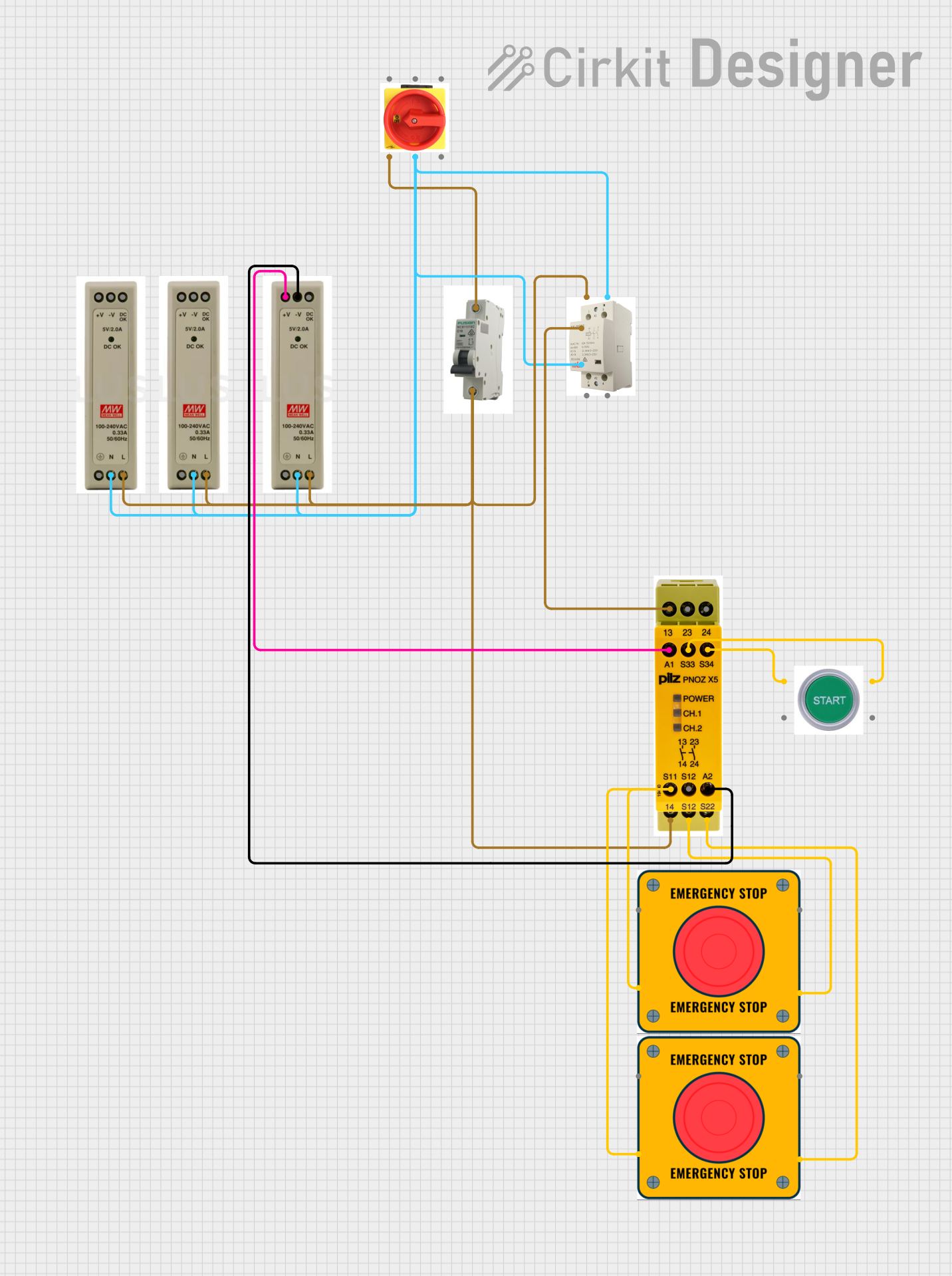
Industrial Power Distribution and Safety Control System
Image of Control Diagram: A project utilizing 2P Breaker in a practical application
This circuit is designed for power distribution and safety control in an industrial setting. It features a main isolator and circuit breaker for power management, multiple PSUs for 5V, 12V, and 24V outputs, and a safety relay system that interfaces with E-stop buttons and a start switch to control a main contactor, ensuring safe operation and emergency power cut-off capabilities.
Cirkit Designer LogoOpen Project in Cirkit Designer
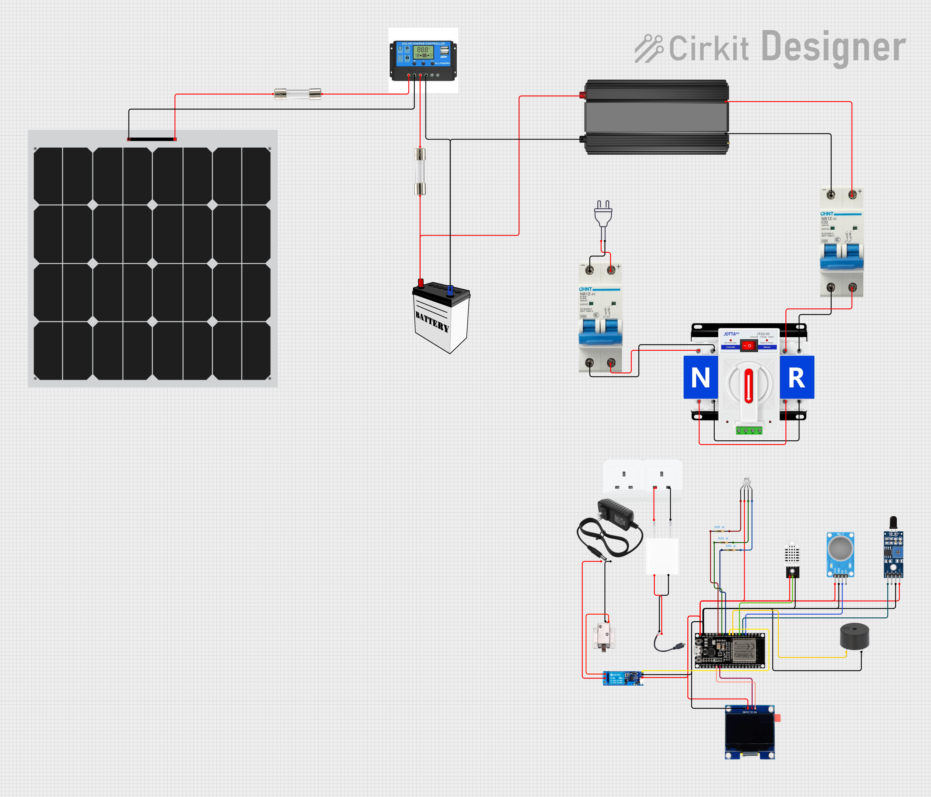
Solar-Powered Environmental Monitoring System with Automatic Transfer Switch and ESP32 Control
Image of Fire exit: A project utilizing 2P Breaker in a practical application
This circuit appears to be a solar power management system with dual power input capability, integrating a solar panel with a charge controller to manage charging a 12V battery and providing power through an inverter for AC loads. It includes safety features such as circuit breakers and fuses, and a dual power automatic transfer switch to alternate between solar and grid power. The system also incorporates an ESP32 microcontroller interfaced with various sensors (MQ-2, SHT113, DHT22), a buzzer for alerts, an OLED display for status output, and a relay module to control a 12V solenoid lock, with power regulation provided by a 5V adapter and resistors for LED current limiting.
Cirkit Designer LogoOpen Project in Cirkit Designer
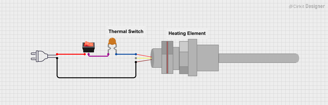
PT100 Temperature Sensor with Rocker Switch and Resettable Fuse
Image of soldering iron: A project utilizing 2P Breaker in a practical application
This circuit is a basic power control system that uses a rocker switch to control the flow of 220V power through a resettable fuse and a PT100 temperature sensor. The switch allows the user to turn the power on or off, while the fuse provides overcurrent protection and the PT100 sensor can be used for temperature monitoring.
Cirkit Designer LogoOpen Project in Cirkit Designer

Explore Projects Built with 2P Breaker

Use Cirkit Designer to design, explore, and prototype these projects online. Some projects support real-time simulation. Click "Open Project" to start designing instantly!
Image of schematic: A project utilizing 2P Breaker in a practical application
AC Bulb Control Circuit with Rocker Switches and Circuit Breaker
This circuit is designed to control multiple AC bulbs using two rocker switches and a circuit breaker for safety. The circuit is powered by a 220V AC source, with the circuit breaker providing protection and the rocker switches allowing selective control of the connected bulbs.
Cirkit Designer LogoOpen Project in Cirkit Designer
Image of Control Diagram: A project utilizing 2P Breaker in a practical application
Industrial Power Distribution and Safety Control System
This circuit is designed for power distribution and safety control in an industrial setting. It features a main isolator and circuit breaker for power management, multiple PSUs for 5V, 12V, and 24V outputs, and a safety relay system that interfaces with E-stop buttons and a start switch to control a main contactor, ensuring safe operation and emergency power cut-off capabilities.
Cirkit Designer LogoOpen Project in Cirkit Designer
Image of Fire exit: A project utilizing 2P Breaker in a practical application
Solar-Powered Environmental Monitoring System with Automatic Transfer Switch and ESP32 Control
This circuit appears to be a solar power management system with dual power input capability, integrating a solar panel with a charge controller to manage charging a 12V battery and providing power through an inverter for AC loads. It includes safety features such as circuit breakers and fuses, and a dual power automatic transfer switch to alternate between solar and grid power. The system also incorporates an ESP32 microcontroller interfaced with various sensors (MQ-2, SHT113, DHT22), a buzzer for alerts, an OLED display for status output, and a relay module to control a 12V solenoid lock, with power regulation provided by a 5V adapter and resistors for LED current limiting.
Cirkit Designer LogoOpen Project in Cirkit Designer
Image of soldering iron: A project utilizing 2P Breaker in a practical application
PT100 Temperature Sensor with Rocker Switch and Resettable Fuse
This circuit is a basic power control system that uses a rocker switch to control the flow of 220V power through a resettable fuse and a PT100 temperature sensor. The switch allows the user to turn the power on or off, while the fuse provides overcurrent protection and the PT100 sensor can be used for temperature monitoring.
Cirkit Designer LogoOpen Project in Cirkit Designer

Technical Specifications

  • Type: 2-pole circuit breaker
  • Rated Voltage: 120/240V AC (typical for residential systems)
  • Rated Current: 10A, 15A, 20A, 30A, or higher (varies by model)
  • Interrupting Capacity: 10kA at 240V AC (varies by model)
  • Trip Mechanism: Thermal-magnetic
  • Mounting Type: DIN rail or panel-mounted (varies by model)
  • Standards Compliance: UL 489, IEC 60947-2

Pin Configuration and Descriptions

The 2P Breaker does not have traditional "pins" like electronic components but instead features terminals for wiring. Below is a description of the terminals:

Terminal Name Description
Line 1 (L1) Input terminal for the first phase of the dual-phase system.
Line 2 (L2) Input terminal for the second phase of the dual-phase system.
Load 1 Output terminal connected to the load for the first phase.
Load 2 Output terminal connected to the load for the second phase.
Ground (if applicable) Some models include a ground terminal for additional safety.

Usage Instructions

  1. Installation:

    • Ensure the power supply is turned off before installation.
    • Mount the breaker securely on a DIN rail or panel, depending on the model.
    • Connect the input terminals (L1 and L2) to the power source.
    • Connect the output terminals (Load 1 and Load 2) to the load (e.g., appliances, circuits).
    • If the breaker includes a ground terminal, connect it to the system ground.
  2. Operation:

    • The breaker will remain in the "ON" position during normal operation.
    • In the event of an overload or short circuit, the breaker will trip to the "OFF" position, disconnecting power.
    • To reset, first identify and resolve the cause of the trip, then switch the breaker back to the "ON" position.
  3. Important Considerations:

    • Always select a breaker with a current rating appropriate for the circuit it protects.
    • Ensure proper torque is applied to terminal screws to avoid loose connections.
    • Do not bypass or modify the breaker, as this compromises its safety features.
  4. Example Circuit: Below is a simple example of how a 2P Breaker might be used in a dual-phase system:

    Power Source (120/240V AC)
        L1  -------------------+------------------- Load 1
                               |
        L2  -------------------+------------------- Load 2
    
    • L1 and L2 are connected to the input terminals of the breaker.
    • Load 1 and Load 2 are connected to the output terminals of the breaker.

Troubleshooting and FAQs

Common Issues

  1. Breaker Trips Frequently:

    • Cause: Overloaded circuit or short circuit.
    • Solution: Reduce the load on the circuit or inspect for wiring faults.
  2. Breaker Does Not Reset:

    • Cause: Persistent fault in the circuit or damaged breaker.
    • Solution: Check the circuit for faults and replace the breaker if necessary.
  3. Loose Connections:

    • Cause: Improperly tightened terminal screws.
    • Solution: Ensure all connections are secure and meet the manufacturer's torque specifications.

FAQs

  1. Can I use a 2P Breaker in a single-phase system?
    Yes, but only one pole will be active. This is not recommended unless specified by the manufacturer.

  2. What is the difference between a 2P Breaker and two single-pole breakers?
    A 2P Breaker is designed to trip both poles simultaneously, ensuring complete disconnection of power in dual-phase systems. Two single-pole breakers do not offer this synchronized protection.

  3. How do I know if my breaker is compatible with my electrical panel?
    Check the manufacturer's specifications for your panel and ensure the breaker matches the panel's type and mounting requirements.

By following this documentation, you can safely and effectively use a 2P Breaker in your electrical systems.