
How to Use Arcade Button (red): Examples, Pinouts, and Specs
 Design with Arcade Button (red) in Cirkit Designer
Introduction
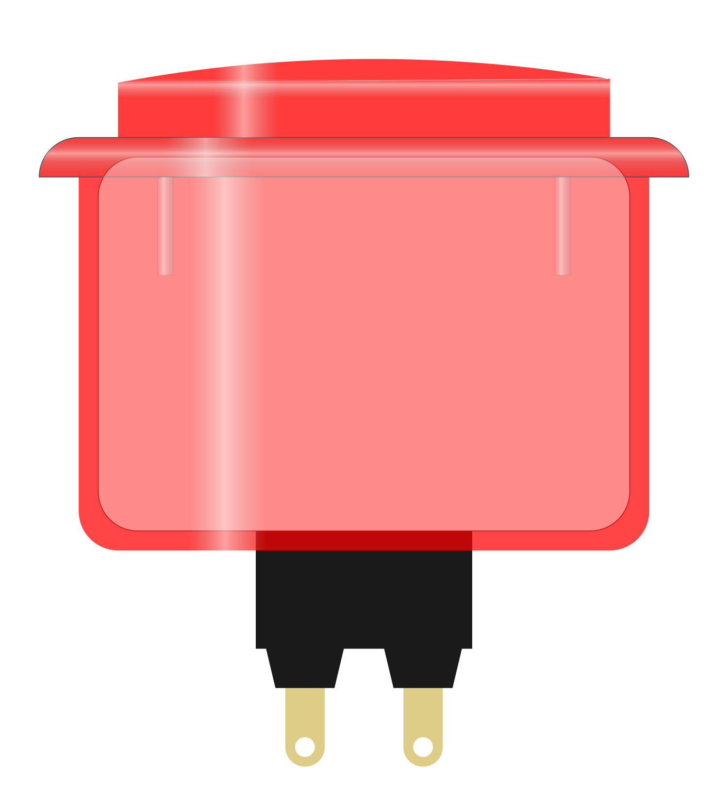
The Arcade Button (Red) is a push-button switch designed for user interaction in electronic projects. It is widely recognized for its bright red color, which ensures high visibility, and its tactile response, which provides satisfying feedback when pressed. This component is commonly used in arcade machines, gaming consoles, DIY electronics, and interactive projects. Its durable construction and ease of use make it a popular choice for hobbyists and professionals alike.
Explore Projects Built with Arcade Button (red)
 Open Project in Cirkit Designer
 Open Project in Cirkit Designer
 Open Project in Cirkit Designer
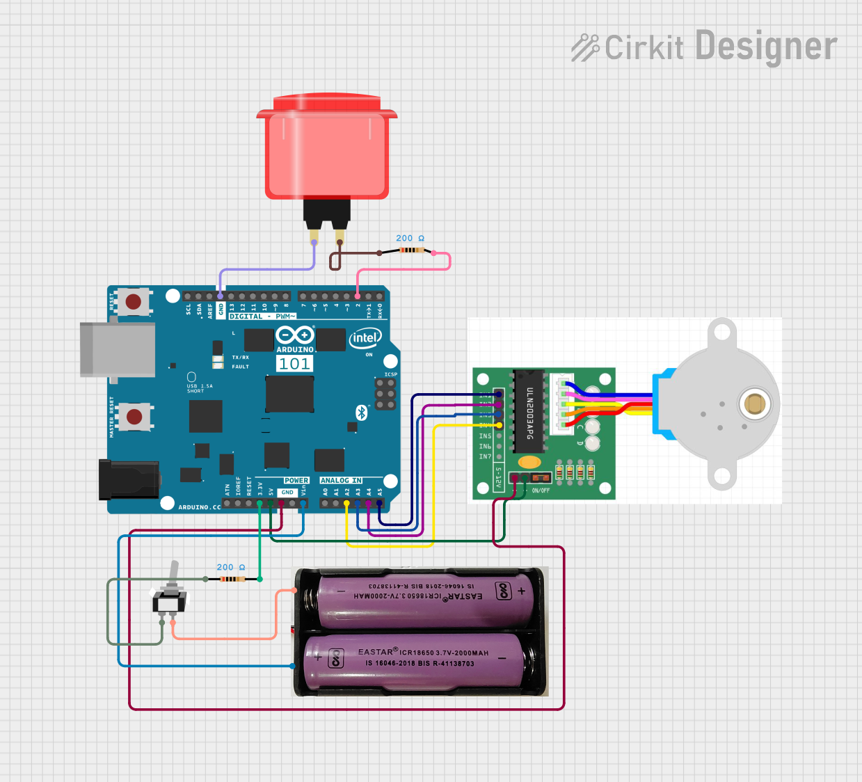 Open Project in Cirkit Designer
Explore Projects Built with Arcade Button (red)
Open Project in Cirkit DesignerOpen Project in Cirkit DesignerOpen Project in Cirkit DesignerOpen Project in Cirkit DesignerCommon Applications:
- Arcade gaming machines
- DIY gaming controllers
- Interactive kiosks
- Educational electronics projects
- Custom control panels
Technical Specifications
The Arcade Button (Red) is a simple, robust component with the following specifications:
| Parameter | Value |
|---|---|
| Button Type | Momentary push-button |
| Color | Red |
| Material | Plastic (housing), metal (contacts) |
| Operating Voltage | 3.3V to 12V (typical) |
| Current Rating | 1A max |
| Contact Resistance | ≤ 50 mΩ |
| Actuation Force | ~150g |
| Mounting Hole Diameter | 24mm |
| Terminal Type | Solder lugs |
| Lifespan | ~1,000,000 cycles |
Pin Configuration and Descriptions
The Arcade Button (Red) typically has two terminals for connection:
| Pin | Description |
|---|---|
| Pin 1 | Normally Open (NO) contact |
| Pin 2 | Common (COM) contact |
- Pin 1 (NO): This terminal connects to the circuit when the button is pressed.
- Pin 2 (COM): This terminal is the common connection point for the circuit.
Usage Instructions
How to Use the Arcade Button in a Circuit
Mounting the Button:
- Drill a 24mm hole in your panel or enclosure.
- Insert the button into the hole and secure it using the included mounting nut.
Wiring the Button:
- Connect Pin 1 (NO) to the input of your circuit (e.g., a microcontroller pin or a signal line).
- Connect Pin 2 (COM) to the ground (GND) or the other side of the circuit.
Testing the Button:
- When the button is pressed, it completes the circuit between Pin 1 and Pin 2, allowing current to flow.
Important Considerations and Best Practices
- Debouncing: Mechanical buttons like this one may produce noise or "bouncing" when pressed. Use a hardware or software debounce mechanism to ensure reliable operation.
- Voltage and Current Ratings: Do not exceed the specified voltage (12V) or current (1A) to avoid damaging the button.
- Secure Connections: Use solder or crimp connectors to ensure a reliable connection to the terminals.
- Mounting: Ensure the button is securely mounted to prevent it from loosening during use.
Example: Connecting to an Arduino UNO
The Arcade Button (Red) can be easily interfaced with an Arduino UNO. Below is an example circuit and code:
Circuit:
- Connect Pin 1 (NO) of the button to Arduino digital pin 2.
- Connect Pin 2 (COM) of the button to the Arduino GND pin.
- Optionally, add a 10kΩ pull-down resistor between digital pin 2 and GND to ensure a stable LOW state when the button is not pressed.
Code:
// Arcade Button Example with Arduino UNO
// This code reads the state of the button and turns on an LED when pressed.

const int buttonPin = 2;  // Pin connected to the button's NO terminal
const int ledPin = 13;    // Pin connected to the onboard LED

void setup() {
  pinMode(buttonPin, INPUT);  // Set button pin as input
  pinMode(ledPin, OUTPUT);   // Set LED pin as output
  digitalWrite(ledPin, LOW); // Ensure LED is off initially
}

void loop() {
  int buttonState = digitalRead(buttonPin); // Read the button state

  if (buttonState == HIGH) {
    // If button is pressed, turn on the LED
    digitalWrite(ledPin, HIGH);
  } else {
    // If button is not pressed, turn off the LED
    digitalWrite(ledPin, LOW);
  }
}
Troubleshooting and FAQs
Common Issues and Solutions
Button Not Responding:
- Cause: Loose or incorrect wiring.
- Solution: Check the connections to ensure Pin 1 and Pin 2 are properly connected.
Button Stuck or Not Clicking:
- Cause: Dirt or debris inside the button mechanism.
- Solution: Clean the button with compressed air or replace it if damaged.
Unstable or Flickering Output:
- Cause: Button bounce or lack of pull-down resistor.
- Solution: Implement a debounce mechanism in software or add a pull-down resistor.
Button Feels Loose:
- Cause: Improper mounting.
- Solution: Tighten the mounting nut securely.
FAQs
Q1: Can I use this button with a Raspberry Pi?
Yes, the Arcade Button (Red) can be used with a Raspberry Pi. Connect it to a GPIO pin and use a pull-up or pull-down resistor as needed.
Q2: Is the button waterproof?
No, this button is not waterproof. Avoid using it in environments with high moisture or water exposure.
Q3: Can I use this button for high-power applications?
No, the button is rated for a maximum of 1A current. For high-power applications, use a relay or transistor to handle the load.
Q4: How do I debounce the button in software?
You can use a simple delay or a debounce library in your microcontroller code to filter out noise caused by button bouncing.
By following this documentation, you can effectively integrate the Arcade Button (Red) into your projects and troubleshoot any issues that arise.