
How to Use Header 2: Examples, Pinouts, and Specs
 Design with Header 2 in Cirkit Designer
Introduction
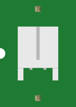
A Header 2 is a type of connector used in electronic circuits to facilitate the connection of multiple wires or components. It typically features two rows of pins, making it ideal for secure and organized connections in compact spaces. Header 2 connectors are widely used in prototyping, PCB designs, and modular systems where reliable and repeatable connections are required.
Explore Projects Built with Header 2
 Open Project in Cirkit Designer
 Open Project in Cirkit Designer
 Open Project in Cirkit Designer
 Open Project in Cirkit Designer
Explore Projects Built with Header 2
Open Project in Cirkit DesignerOpen Project in Cirkit DesignerOpen Project in Cirkit DesignerOpen Project in Cirkit DesignerCommon Applications and Use Cases
- Connecting PCBs in modular electronic systems
- Interfacing sensors, displays, or other peripherals with microcontrollers
- Prototyping circuits on breadboards or custom PCBs
- Creating detachable connections in embedded systems
- Used in ribbon cable assemblies for organized wiring
Technical Specifications
Key Technical Details
- Number of Pins: Typically ranges from 2x2 (4 pins) to 2x40 (80 pins)
- Pin Pitch: Standard 2.54 mm (0.1 inch) spacing
- Current Rating: Typically 1A to 3A per pin
- Voltage Rating: Up to 250V (varies by manufacturer)
- Operating Temperature: -40°C to +105°C
- Material: Pins are usually made of brass or phosphor bronze with gold or tin plating for corrosion resistance
- Mounting Type: Through-hole or surface-mount
Pin Configuration and Descriptions
The pin configuration of a Header 2 connector depends on the number of pins and rows. Below is an example for a 2x4 (8-pin) Header 2 connector:
| Pin Number | Description |
|---|---|
| 1 | Signal or Power (Row 1, Pin 1) |
| 2 | Signal or Power (Row 1, Pin 2) |
| 3 | Signal or Power (Row 1, Pin 3) |
| 4 | Signal or Power (Row 1, Pin 4) |
| 5 | Signal or Power (Row 2, Pin 1) |
| 6 | Signal or Power (Row 2, Pin 2) |
| 7 | Signal or Power (Row 2, Pin 3) |
| 8 | Signal or Power (Row 2, Pin 4) |
Note: The specific pin assignments depend on the circuit design and application.
Usage Instructions
How to Use the Component in a Circuit
- Determine the Pinout: Refer to the circuit schematic or datasheet to identify the function of each pin.
- Soldering: If using a through-hole Header 2, insert the pins into the PCB and solder them securely. For surface-mount headers, use a reflow soldering process.
- Connecting Wires or Components: Use female connectors, jumper wires, or ribbon cables to connect to the Header 2 pins.
- Ensure Proper Orientation: Align the connector correctly to avoid reversed connections.
- Test the Connection: Verify continuity and functionality using a multimeter or by powering the circuit.
Important Considerations and Best Practices
- Avoid Overcurrent: Do not exceed the current rating of the pins to prevent overheating or damage.
- Use Proper Tools: Use a soldering iron with a fine tip for precise soldering and avoid bridging adjacent pins.
- Secure Connections: Use locking connectors or headers with friction locks for applications subject to vibration.
- Label Pins: Clearly label the pin functions on the PCB to avoid confusion during assembly or troubleshooting.
Example: Connecting a Header 2 to an Arduino UNO
Below is an example of using a 2x4 Header 2 to connect an external sensor to an Arduino UNO:
// Example code to read data from a sensor connected via a Header 2 connector
// Pin 1: VCC (5V), Pin 2: GND, Pin 3: Data, Pin 4: Clock

#define DATA_PIN 2  // Connect Header 2 Pin 3 to Arduino digital pin 2
#define CLOCK_PIN 3 // Connect Header 2 Pin 4 to Arduino digital pin 3

void setup() {
  pinMode(DATA_PIN, INPUT);  // Set data pin as input
  pinMode(CLOCK_PIN, OUTPUT); // Set clock pin as output
  Serial.begin(9600); // Initialize serial communication
}

void loop() {
  digitalWrite(CLOCK_PIN, HIGH); // Generate clock signal
  delay(1);                      // Short delay for timing
  digitalWrite(CLOCK_PIN, LOW);
  delay(1);

  int sensorValue = digitalRead(DATA_PIN); // Read sensor data
  Serial.println(sensorValue); // Print sensor value to serial monitor
  delay(100); // Delay for readability
}
Note: Adjust the pin assignments and code logic based on your specific application and sensor.
Troubleshooting and FAQs
Common Issues Users Might Face
- Loose Connections: Poor contact between the Header 2 pins and the mating connector can cause intermittent signals.
- Solution: Ensure the connectors are fully seated and use locking connectors if necessary.
- Short Circuits: Adjacent pins may short if soldering is not done carefully.
- Solution: Inspect solder joints and use a multimeter to check for shorts.
- Incorrect Pinout: Miswiring can lead to non-functional circuits or damage to components.
- Solution: Double-check the pinout and connections before powering the circuit.
- Corrosion or Oxidation: Over time, the pins may corrode, leading to poor conductivity.
- Solution: Use gold-plated headers for better durability and clean the pins periodically.
FAQs
Q1: Can I use a Header 2 connector for high-frequency signals?
A1: Yes, but ensure the connector and PCB layout are designed to minimize signal integrity issues such as crosstalk and impedance mismatch.
Q2: What is the difference between a Header 2 and a single-row header?
A2: A Header 2 has two rows of pins, allowing for more connections in a compact space, whereas a single-row header has only one row of pins.
Q3: How do I choose the right Header 2 for my project?
A3: Consider the number of pins, pin pitch, current and voltage ratings, and whether you need through-hole or surface-mount headers.
Q4: Can I cut a longer Header 2 to the desired size?
A4: Yes, you can cut a longer header to the required size using a fine saw or wire cutters, but ensure the cut is clean and does not damage the pins.
By following this documentation, you can effectively use a Header 2 connector in your electronic projects!