
How to Use CY8CPROTO-062-4343W: Examples, Pinouts, and Specs
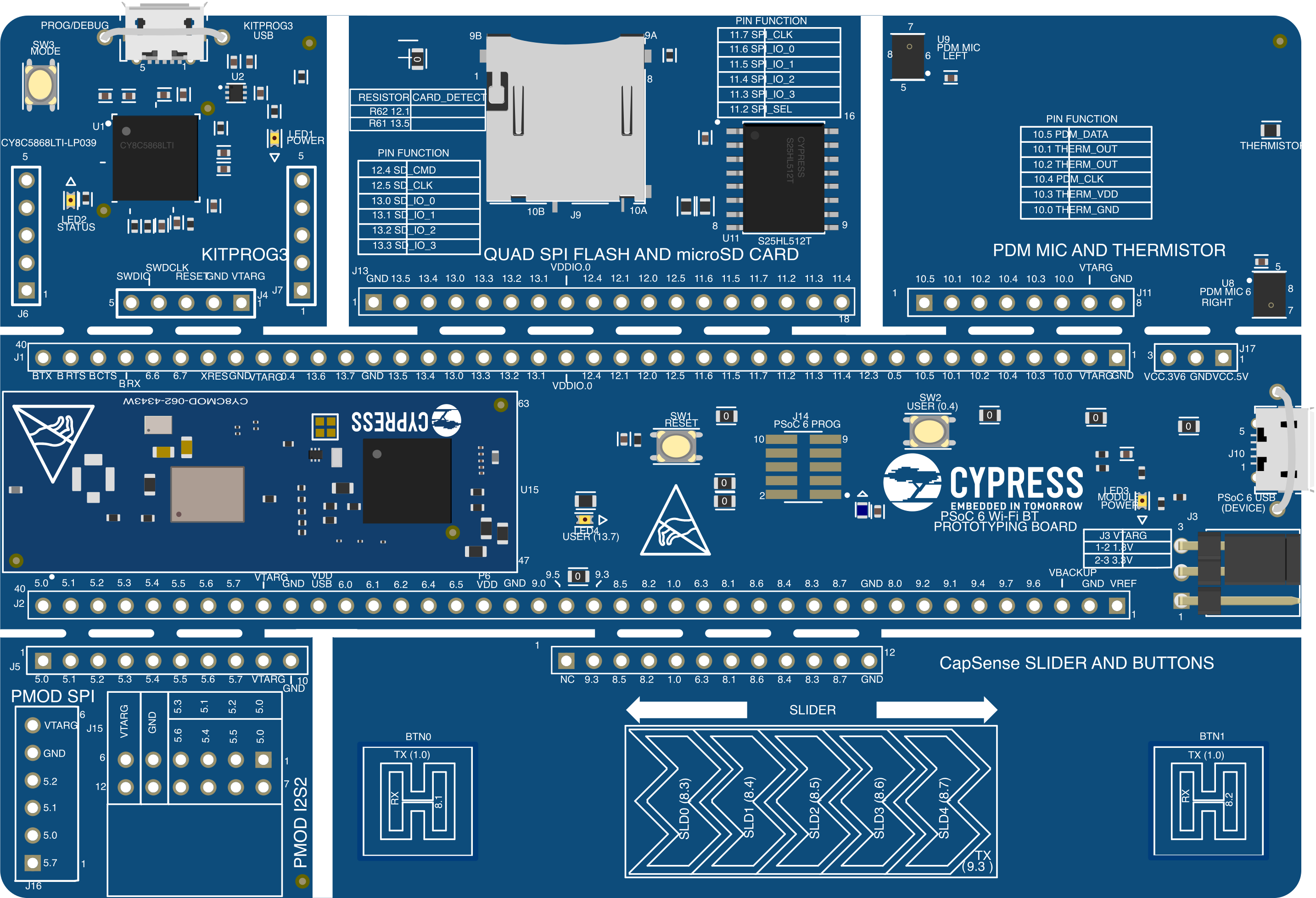
 Design with CY8CPROTO-062-4343W in Cirkit Designer
Introduction
The CY8CPROTO-062-4343W is a development kit manufactured by Infineon Technologies. It features the PSoC 6 microcontroller, a dual-core MCU with ultra-low-power performance, integrated Wi-Fi, and Bluetooth capabilities. This kit is designed for rapid prototyping and is ideal for Internet of Things (IoT) applications, wearable devices, and smart home solutions.
With its rich set of peripherals, onboard sensors, and wireless connectivity, the CY8CPROTO-062-4343W provides developers with a versatile platform to create and test innovative designs quickly.
Explore Projects Built with CY8CPROTO-062-4343W
 Open Project in Cirkit Designer
 Open Project in Cirkit Designer
 Open Project in Cirkit Designer
 Open Project in Cirkit Designer
Explore Projects Built with CY8CPROTO-062-4343W
Open Project in Cirkit DesignerOpen Project in Cirkit DesignerOpen Project in Cirkit DesignerOpen Project in Cirkit DesignerCommon Applications and Use Cases
- IoT devices and smart home automation
- Wearable technology
- Industrial IoT and sensor networks
- Wireless communication systems
- Low-power embedded systems
Technical Specifications
Key Technical Details
| Feature | Specification |
|---|---|
| Microcontroller | PSoC 6 (CY8C624ABZI-D44) |
| Core Architecture | Dual-core: Arm® Cortex®-M4 (up to 150 MHz) and Cortex®-M0+ (up to 100 MHz) |
| Flash Memory | 1 MB |
| SRAM | 288 KB |
| Connectivity | Wi-Fi (802.11b/g/n) and Bluetooth 5.0 |
| Operating Voltage | 2.7V to 3.6V |
| Power Supply Options | USB or external power |
| Debug Interface | SWD (Serial Wire Debug) |
| Dimensions | 50 mm x 20 mm |
| Operating Temperature Range | -40°C to +85°C |
Pin Configuration and Descriptions
The CY8CPROTO-062-4343W features a 44-pin layout. Below is a summary of key pins:
| Pin Name | Description |
|---|---|
| VDD | Main power supply input (3.3V typical) |
| GND | Ground connection |
| SWDIO | Serial Wire Debug I/O for programming and debugging |
| SWCLK | Serial Wire Debug clock input |
| P0.x - P12.x | General-purpose I/O pins (GPIO) |
| TXD/RXD | UART transmit/receive pins for serial communication |
| SDA/SCL | I2C data and clock lines |
| MISO/MOSI/SCK | SPI interface pins (Master In Slave Out, Master Out Slave In, Serial Clock) |
| RESET | Active-low reset pin |
Usage Instructions
How to Use the CY8CPROTO-062-4343W in a Circuit
Powering the Board:
- Connect the board to a USB power source using a micro-USB cable. Alternatively, supply 3.3V to the VDD pin.
- Ensure the GND pin is connected to the ground of your circuit.
Programming the Board:
- Use the onboard KitProg3 programmer/debugger for flashing firmware. Connect the board to your PC via USB and use tools like ModusToolbox or PSoC Creator.
- The SWDIO and SWCLK pins can also be used for external debugging.
Connecting Peripherals:
- Use the GPIO pins (P0.x to P12.x) for interfacing with external sensors, actuators, or other devices.
- For wireless communication, configure the onboard Wi-Fi and Bluetooth modules using the provided APIs in the ModusToolbox software.
Example Circuit:
- Connect an LED to a GPIO pin (e.g., P0.3) with a current-limiting resistor.
- Use the following code to blink the LED.
Example Code for Arduino IDE
Although the CY8CPROTO-062-4343W is typically programmed using ModusToolbox, it can also be used with Arduino IDE. Below is an example to blink an LED connected to GPIO pin P0.3:
// Include necessary libraries
#include <Arduino.h>

// Define the GPIO pin for the LED
#define LED_PIN 3  // P0.3 corresponds to pin 3 in Arduino mapping

void setup() {
  // Set the LED pin as an output
  pinMode(LED_PIN, OUTPUT);
}

void loop() {
  // Turn the LED on
  digitalWrite(LED_PIN, HIGH);
  delay(1000);  // Wait for 1 second

  // Turn the LED off
  digitalWrite(LED_PIN, LOW);
  delay(1000);  // Wait for 1 second
}
Important Considerations and Best Practices
- Power Supply: Ensure the board is powered within the specified voltage range (2.7V to 3.6V).
- Static Protection: Handle the board with care to avoid damage from electrostatic discharge (ESD).
- Firmware Updates: Regularly update the KitProg3 firmware for compatibility with the latest tools.
- Wireless Configuration: Use the ModusToolbox Wi-Fi and Bluetooth libraries for seamless wireless communication.
Troubleshooting and FAQs
Common Issues and Solutions
Board Not Detected by PC:
- Ensure the USB cable is properly connected and functional.
- Verify that the KitProg3 firmware is up to date.
- Check the USB drivers on your PC.
Wi-Fi or Bluetooth Not Working:
- Confirm that the wireless module is enabled in your firmware.
- Check the antenna connection and ensure no physical damage.
- Verify the Wi-Fi credentials or Bluetooth pairing settings.
Program Fails to Upload:
- Ensure the board is in programming mode (check the status LED).
- Verify the SWD connections if using an external debugger.
- Restart the board and try again.
GPIO Pins Not Responding:
- Check the pin configuration in your code.
- Ensure no conflicting peripherals are using the same pins.
- Test the pins with a multimeter to verify electrical connections.
FAQs
Q: Can I use the CY8CPROTO-062-4343W with Arduino IDE?
A: Yes, the board can be programmed using Arduino IDE, but it is primarily designed for use with ModusToolbox or PSoC Creator.
Q: What is the maximum range of the onboard Bluetooth module?
A: The Bluetooth module supports a range of up to 10 meters in typical conditions, depending on environmental factors.
Q: How do I reset the board to factory settings?
A: Press and hold the reset button for 10 seconds while powering the board. This will restore the default firmware.
Q: Can I use external sensors with this board?
A: Yes, the GPIO pins support interfacing with a wide range of external sensors and devices.
This documentation provides a comprehensive guide to using the CY8CPROTO-062-4343W development kit. For further assistance, refer to the official Infineon documentation or community forums.