How to Use Kontaktor 1: Examples, Pinouts, and Specs
Introduction
The Kontaktor 1, manufactured by Schneider (Part ID: High Volt), is an electrically controlled switch designed for switching power circuits. Unlike standard relays, contactors are specifically engineered to handle higher currents, making them ideal for industrial and motor control applications. This robust component is widely used in automation systems, HVAC systems, and heavy machinery to control high-power loads safely and efficiently.
Explore Projects Built with Kontaktor 1


Explore Projects Built with Kontaktor 1
Common Applications
- Motor control in industrial machinery
- HVAC systems for switching compressors and fans
- Lighting control in large-scale installations
- Power distribution systems
- Renewable energy systems (e.g., solar inverters)
Technical Specifications
Key Technical Details
| Parameter | Value |
|---|---|
| Manufacturer | Schneider |
| Part ID | High Volt |
| Rated Voltage | 24V DC (coil voltage) |
| Rated Current | 40A (main contacts) |
| Number of Poles | 3P (Three-pole contactor) |
| Contact Configuration | Normally Open (NO) |
| Operating Temperature | -25°C to +60°C |
| Mechanical Durability | 10 million operations |
| Electrical Durability | 1 million operations |
| Mounting Type | DIN Rail or Panel Mount |
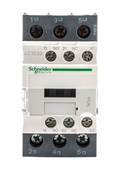
Pin Configuration and Descriptions
The Kontaktor 1 has a straightforward pin layout for both the control coil and the main power contacts. Below is the pin configuration:
Control Coil Terminals
| Pin Number | Label | Description |
|---|---|---|
| A1 | + | Positive terminal for the coil |
| A2 | - | Negative terminal for the coil |
Main Power Contacts
| Pin Number | Label | Description |
|---|---|---|
| L1 | IN1 | Input for phase 1 of the power circuit |
| L2 | IN2 | Input for phase 2 of the power circuit |
| L3 | IN3 | Input for phase 3 of the power circuit |
| T1 | OUT1 | Output for phase 1 of the power circuit |
| T2 | OUT2 | Output for phase 2 of the power circuit |
| T3 | OUT3 | Output for phase 3 of the power circuit |
Usage Instructions
How to Use the Kontaktor 1 in a Circuit
- Power the Coil: Connect the control voltage (24V DC) to the A1 and A2 terminals. Ensure the polarity is correct.
- Connect the Load: Wire the high-power load (e.g., motor, lighting system) to the main power contacts (L1, L2, L3 for input and T1, T2, T3 for output).
- Control the Contactor: Use a low-power control circuit (e.g., a switch, PLC, or microcontroller) to energize the coil and activate the contactor.
- Ensure Proper Mounting: Secure the contactor on a DIN rail or panel mount for stable operation.
Important Considerations and Best Practices
- Overcurrent Protection: Always use appropriate fuses or circuit breakers to protect the contactor and connected load.
- Avoid Coil Overvoltage: Ensure the control voltage does not exceed the rated 24V DC to prevent coil damage.
- Use Surge Suppressors: Install surge suppressors or snubber circuits across the coil terminals to reduce voltage spikes during deactivation.
- Check Contact Ratings: Verify that the contactor's current and voltage ratings match the requirements of your load.
- Regular Maintenance: Periodically inspect the contactor for wear and tear, especially in high-duty-cycle applications.
Example: Connecting Kontaktor 1 to an Arduino UNO
The Kontaktor 1 can be controlled using an Arduino UNO. Below is an example circuit and code to toggle the contactor using a digital output pin.
Circuit Setup
- Connect the A1 terminal of the contactor to the Arduino's digital pin (e.g., D8) through a transistor and a flyback diode.
- Connect the A2 terminal to the ground (GND) of the Arduino.
- Use an external 24V DC power supply for the contactor coil.
Arduino Code
// Define the pin connected to the contactor's control circuit
const int contactorPin = 8;

void setup() {
  // Set the contactor pin as an output
  pinMode(contactorPin, OUTPUT);
}

void loop() {
  // Activate the contactor
  digitalWrite(contactorPin, HIGH);
  delay(5000); // Keep the contactor ON for 5 seconds

  // Deactivate the contactor
  digitalWrite(contactorPin, LOW);
  delay(5000); // Keep the contactor OFF for 5 seconds
}
Troubleshooting and FAQs
Common Issues and Solutions
| Issue | Possible Cause | Solution |
|---|---|---|
| Contactor does not activate | No control voltage at A1 and A2 | Check the control circuit and power supply |
| Coil overheating | Overvoltage or prolonged activation | Verify the control voltage and duty cycle |
| Contacts not closing properly | Worn or damaged contacts | Inspect and replace the contactor if needed |
| Excessive noise during operation | Loose mounting or electrical interference | Tighten mounting screws and check wiring |
FAQs
Q1: Can the Kontaktor 1 handle DC loads?
A1: Yes, but ensure the load current and voltage are within the contactor's DC rating. Consult the datasheet for specific DC load ratings.
Q2: How do I reduce arcing on the contacts?
A2: Use arc suppression devices, such as RC snubber circuits or varistors, to minimize arcing during switching.
Q3: Can I use the Kontaktor 1 in outdoor environments?
A3: The contactor is not weatherproof. Use an appropriate enclosure to protect it from moisture and dust.
Q4: What is the lifespan of the Kontaktor 1?
A4: The mechanical durability is rated at 10 million operations, while the electrical durability is rated at 1 million operations under normal conditions.