
How to Use Quad Comparator: Examples, Pinouts, and Specs

 Design with Quad Comparator in Cirkit Designer
Introduction
The LM239 is a quad comparator integrated circuit manufactured by Texas Instruments. It contains four independent voltage comparators, each capable of comparing two input voltages and outputting a digital signal to indicate which input is higher. This component is widely used in signal conditioning, level detection, and analog-to-digital conversion applications. Its robust design and low power consumption make it suitable for a variety of industrial, automotive, and consumer electronics applications.
Explore Projects Built with Quad Comparator
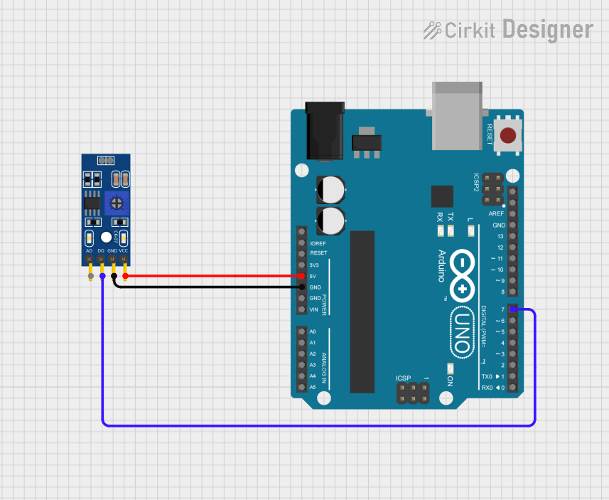 Open Project in Cirkit Designer
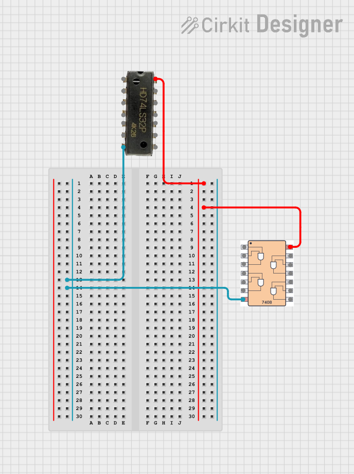 Open Project in Cirkit Designer
 Open Project in Cirkit Designer
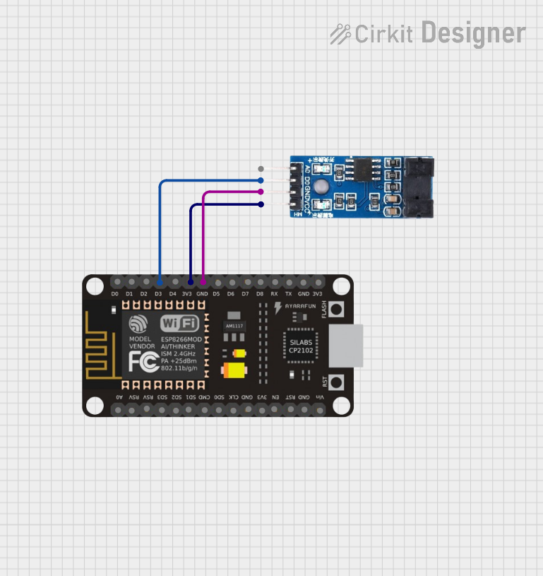 Open Project in Cirkit Designer
Explore Projects Built with Quad Comparator
Open Project in Cirkit DesignerOpen Project in Cirkit DesignerOpen Project in Cirkit DesignerOpen Project in Cirkit DesignerCommon Applications
- Zero-crossing detectors
- Voltage level detection
- Pulse-width modulation (PWM) circuits
- Analog-to-digital conversion (ADC) pre-processing
- Oscillator circuits
- Window comparators
Technical Specifications
Key Technical Details
| Parameter | Value |
|---|---|
| Supply Voltage (Vcc) | 2V to 36V (single supply) or ±1V to ±18V |
| Input Offset Voltage | 2mV (typical) |
| Input Bias Current | 25nA (typical) |
| Output Sink Current | 6mA (typical) |
| Response Time | 1.3µs (typical, with 5mV overdrive) |
| Operating Temperature Range | -40°C to +85°C |
| Package Types | SOIC, PDIP, TSSOP |
Pin Configuration and Descriptions
The LM239 is typically available in a 14-pin dual in-line package (DIP) or surface-mount package. Below is the pinout and description:
| Pin Number | Pin Name | Description |
|---|---|---|
| 1 | OUTPUT1 | Output of Comparator 1 |
| 2 | INPUT1- | Inverting Input of Comparator 1 |
| 3 | INPUT1+ | Non-Inverting Input of Comparator 1 |
| 4 | VCC- (GND) | Negative Power Supply (Ground) |
| 5 | INPUT2+ | Non-Inverting Input of Comparator 2 |
| 6 | INPUT2- | Inverting Input of Comparator 2 |
| 7 | OUTPUT2 | Output of Comparator 2 |
| 8 | OUTPUT3 | Output of Comparator 3 |
| 9 | INPUT3- | Inverting Input of Comparator 3 |
| 10 | INPUT3+ | Non-Inverting Input of Comparator 3 |
| 11 | VCC+ | Positive Power Supply |
| 12 | INPUT4+ | Non-Inverting Input of Comparator 4 |
| 13 | INPUT4- | Inverting Input of Comparator 4 |
| 14 | OUTPUT4 | Output of Comparator 4 |
Usage Instructions
How to Use the LM239 in a Circuit
- Power Supply: Connect the positive power supply (Vcc+) to pin 11 and the ground (Vcc-) to pin 4. Ensure the supply voltage is within the range of 2V to 36V for single-supply operation or ±1V to ±18V for dual-supply operation.
- Input Connections: Connect the voltage signals to be compared to the inverting (INPUT-) and non-inverting (INPUT+) pins of the desired comparator.
- Output: The output pins (OUTPUT1 to OUTPUT4) will provide a digital signal. The output will be low (close to ground) if the inverting input voltage is higher than the non-inverting input voltage, and high (close to Vcc) otherwise.
- Pull-Up Resistor: Since the LM239 has an open-collector output, connect a pull-up resistor (typically 10kΩ) between the output pin and the positive supply voltage (Vcc+).
Important Considerations and Best Practices
- Input Voltage Range: Ensure the input voltages remain within the common-mode voltage range, which is typically 0V to (Vcc - 1.5V).
- Bypass Capacitor: Place a decoupling capacitor (e.g., 0.1µF) close to the power supply pins to reduce noise and improve stability.
- Unused Comparators: If any comparators are unused, connect their inputs to a fixed voltage within the input voltage range to prevent erratic behavior.
- Output Loading: Avoid excessive loading on the output pins to maintain proper operation and response time.
Example: Connecting LM239 to an Arduino UNO
The LM239 can be used with an Arduino UNO for applications such as voltage level detection. Below is an example circuit and code for detecting whether an input voltage exceeds a threshold.
Circuit Description
- Connect the non-inverting input (INPUT1+) to the voltage signal to be monitored.
- Connect the inverting input (INPUT1-) to a reference voltage (e.g., 2.5V from a voltage divider).
- Connect the output (OUTPUT1) to a digital input pin on the Arduino (e.g., pin 2).
- Use a pull-up resistor (10kΩ) on the output pin.
Arduino Code
const int comparatorOutputPin = 2; // LM239 OUTPUT1 connected to Arduino pin 2
const int ledPin = 13;            // Onboard LED for indication

void setup() {
  pinMode(comparatorOutputPin, INPUT); // Set comparator output as input
  pinMode(ledPin, OUTPUT);            // Set LED pin as output
}

void loop() {
  int comparatorState = digitalRead(comparatorOutputPin);
  // Read the state of the comparator output

  if (comparatorState == HIGH) {
    digitalWrite(ledPin, HIGH); // Turn on LED if input voltage > reference
  } else {
    digitalWrite(ledPin, LOW);  // Turn off LED otherwise
  }
}
Troubleshooting and FAQs
Common Issues and Solutions
No Output Signal:
- Cause: Missing pull-up resistor on the output pin.
- Solution: Add a pull-up resistor (e.g., 10kΩ) between the output pin and Vcc.
Erratic Behavior:
- Cause: Floating inputs on unused comparators.
- Solution: Tie unused inputs to a fixed voltage within the input voltage range.
Slow Response Time:
- Cause: Excessive capacitive loading on the output pin.
- Solution: Minimize capacitive loading and use appropriate pull-up resistor values.
Incorrect Output Voltage Levels:
- Cause: Input voltages exceed the common-mode voltage range.
- Solution: Ensure input voltages are within the specified range (0V to Vcc - 1.5V).
FAQs
Q1: Can the LM239 be used with a single power supply?
A1: Yes, the LM239 supports single-supply operation with a voltage range of 2V to 36V.
Q2: What is the purpose of the pull-up resistor on the output?
A2: The LM239 has an open-collector output, which requires a pull-up resistor to generate a valid high-level output voltage.
Q3: Can the LM239 handle AC signals?
A3: Yes, the LM239 can compare AC signals, but ensure the input voltages remain within the common-mode voltage range.
Q4: What is the maximum output current?
A4: The LM239 can sink up to 6mA of current at the output. Avoid exceeding this limit to prevent damage.