How to Use Driver ULN2003 for Stepper: Examples, Pinouts, and Specs

Introduction
The ULN2003 is a high-voltage, high-current Darlington transistor array designed to drive inductive loads such as stepper motors, relays, solenoids, and LEDs. It features seven open-collector outputs, each capable of sinking significant current, making it an excellent choice for interfacing low-power microcontrollers with high-power devices. The ULN2003 is widely used in stepper motor driver circuits due to its simplicity, reliability, and ability to handle high currents.
Explore Projects Built with Driver ULN2003 for Stepper

Explore Projects Built with Driver ULN2003 for Stepper
Common Applications and Use Cases
- Driving stepper motors in robotics and automation systems
- Controlling relays and solenoids in industrial applications
- LED matrix and display control
- Interfacing microcontrollers with high-power devices
Technical Specifications
Key Technical Details
- Supply Voltage (VCE): Up to 50V
- Output Current (per channel): 500mA (maximum)
- Input Voltage (VIH): 2.7V to 5V (logic high)
- Number of Channels: 7
- Output Type: Open-collector
- Integrated Freewheeling Diodes: Yes (for inductive load protection)
- Package Type: DIP-16, SOP-16, or other variants
Pin Configuration and Descriptions
The ULN2003 has 16 pins, with the following configuration:
| Pin Number | Pin Name | Description |
|---|---|---|
| 1-7 | IN1-IN7 | Input pins for channels 1 to 7. Connect to the microcontroller or control logic. |
| 8 | GND | Ground pin. Connect to the ground of the power supply. |
| 9 | COM | Common cathode for freewheeling diodes. Connect to the positive supply of the load. |
| 10-16 | OUT7-OUT1 | Output pins for channels 7 to 1. Connect to the load (e.g., stepper motor coils). |
Usage Instructions
How to Use the ULN2003 in a Circuit
Power Supply:
- Connect the GND pin (Pin 8) to the ground of the power supply.
- Connect the COM pin (Pin 9) to the positive supply voltage of the load (e.g., 12V for a stepper motor).
Inputs:
- Connect the IN1-IN7 pins to the microcontroller's GPIO pins. These pins accept logic-level signals (e.g., 3.3V or 5V).
Outputs:
- Connect the OUT1-OUT7 pins to the load terminals (e.g., stepper motor coils, relays, or LEDs).
Freewheeling Diodes:
- The ULN2003 includes built-in freewheeling diodes to protect against voltage spikes generated by inductive loads. Ensure the COM pin is connected to the load's positive supply.
Stepper Motor Control:
- For stepper motors, connect the motor's coil terminals to the output pins (OUT1-OUT4 for a unipolar stepper motor). Use a microcontroller to send the appropriate step sequence to the input pins (IN1-IN4).
Important Considerations and Best Practices
- Ensure the total current drawn by all channels does not exceed the package's maximum power dissipation.
- Use a heat sink or proper ventilation if driving high-current loads continuously.
- Verify the input logic levels are compatible with the microcontroller's GPIO pins.
- For stepper motors, use a proper stepping sequence (e.g., full-step or half-step) to ensure smooth operation.
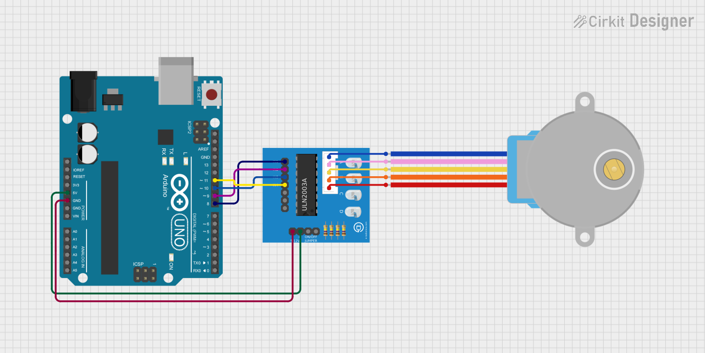
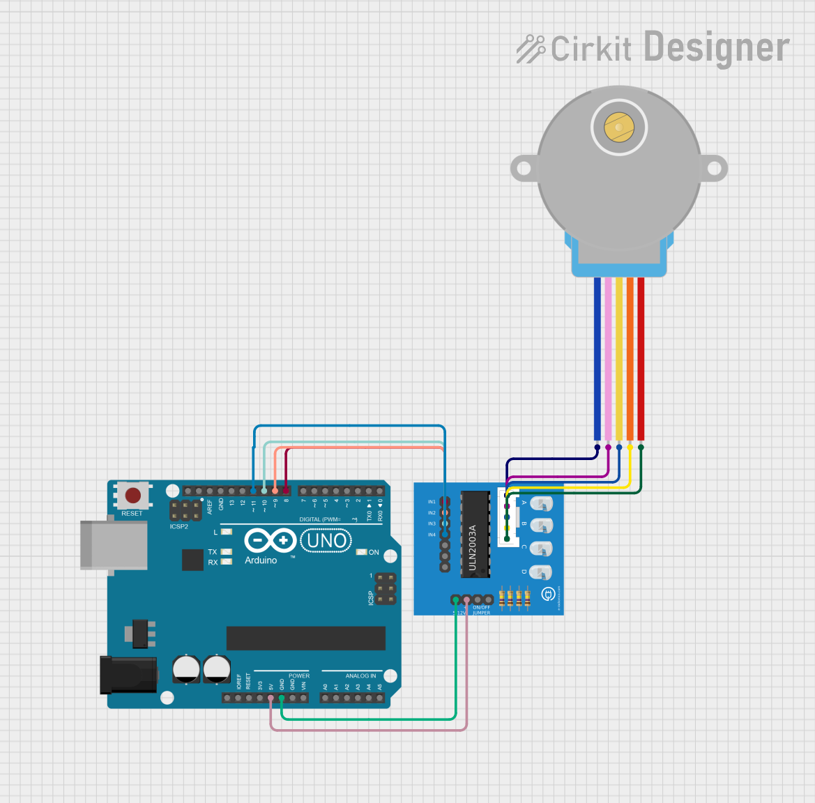
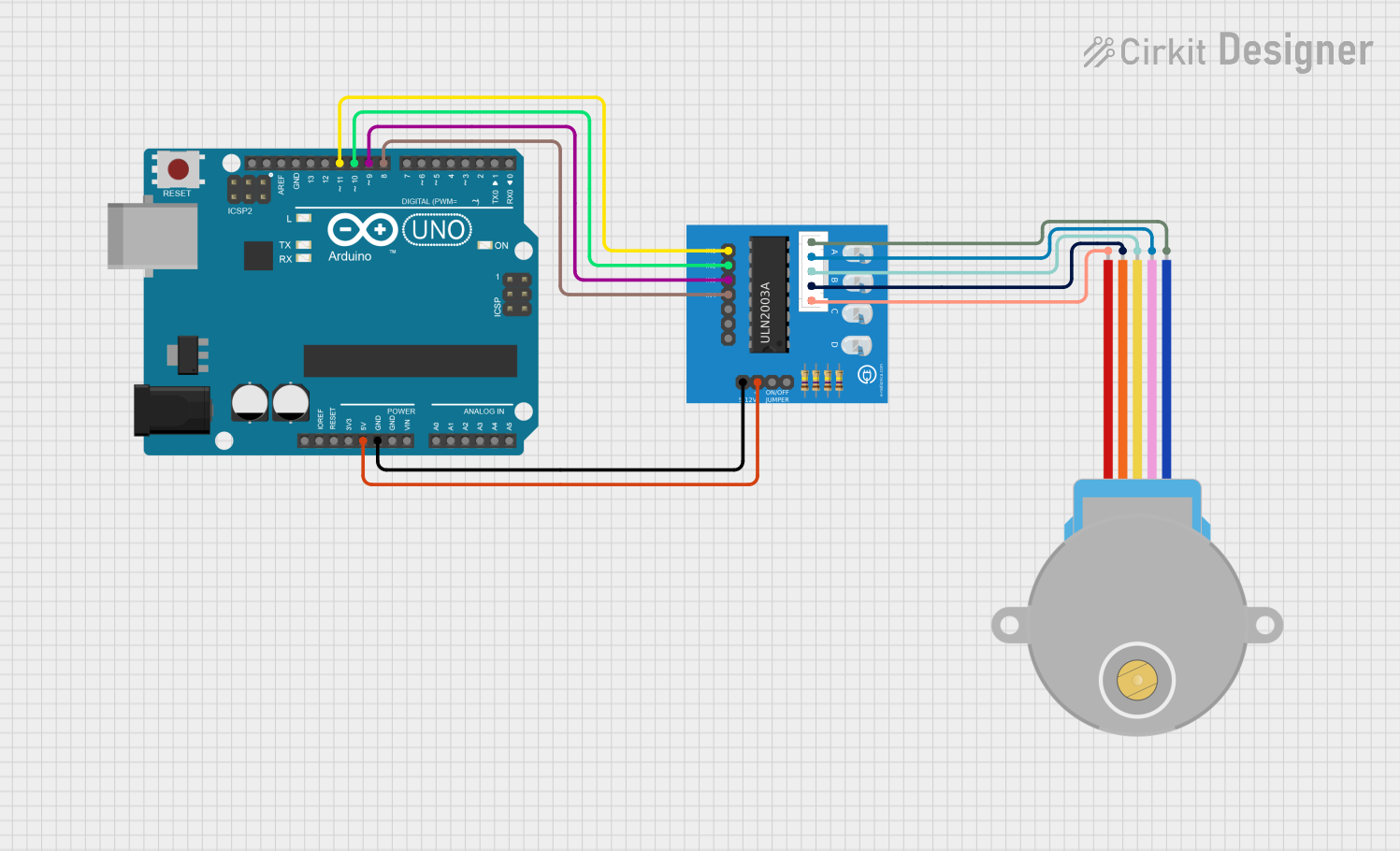
Example: Using ULN2003 with Arduino UNO to Drive a Stepper Motor
Below is an example of controlling a 28BYJ-48 stepper motor using the ULN2003 and Arduino UNO:
// Include the Arduino Stepper library
#include <Stepper.h>

// Define the number of steps per revolution for the 28BYJ-48 motor
#define STEPS_PER_REV 2048

// Initialize the Stepper library with the ULN2003 pins
// Connect IN1-IN4 of ULN2003 to Arduino pins 8, 9, 10, and 11
Stepper stepper(STEPS_PER_REV, 8, 10, 9, 11);

void setup() {
  // Set the speed of the stepper motor (in RPM)
  stepper.setSpeed(10); // 10 RPM
  Serial.begin(9600);
  Serial.println("Stepper Motor Control Initialized");
}

void loop() {
  // Rotate the motor one full revolution clockwise
  Serial.println("Rotating clockwise...");
  stepper.step(STEPS_PER_REV);

  delay(1000); // Wait for 1 second

  // Rotate the motor one full revolution counterclockwise
  Serial.println("Rotating counterclockwise...");
  stepper.step(-STEPS_PER_REV);

  delay(1000); // Wait for 1 second
}
Notes:
- Ensure the stepper motor's power supply matches its voltage and current requirements.
- The ULN2003 board often comes with an LED indicator for each channel, which helps in debugging.
Troubleshooting and FAQs
Common Issues and Solutions
Stepper Motor Not Moving:
- Cause: Incorrect wiring between the ULN2003 and the stepper motor.
- Solution: Double-check the connections between the ULN2003 output pins and the stepper motor coils. Ensure the input pins are receiving the correct step sequence.
Overheating of ULN2003:
- Cause: Excessive current draw from the load.
- Solution: Verify the load's current requirements and ensure it does not exceed 500mA per channel. Use a heat sink if necessary.
No Output Signal:
- Cause: Incorrect input logic levels or disconnected input pins.
- Solution: Ensure the input pins are connected to the microcontroller and receiving the correct logic signals.
Voltage Spikes or Noise:
- Cause: Inductive loads generating back EMF.
- Solution: Ensure the COM pin is connected to the load's positive supply to utilize the built-in freewheeling diodes.
FAQs
Q1: Can I use the ULN2003 to drive a bipolar stepper motor?
A1: No, the ULN2003 is designed for unipolar stepper motors. For bipolar stepper motors, consider using an H-bridge driver like the L298N.
Q2: What is the maximum number of stepper motors I can control with one ULN2003?
A2: You can control one unipolar stepper motor with four coils using four channels of the ULN2003. The remaining three channels can be used for other loads.
Q3: Do I need external diodes for inductive loads?
A3: No, the ULN2003 has built-in freewheeling diodes to protect against voltage spikes from inductive loads.
Q4: Can I use the ULN2003 with a 3.3V microcontroller?
A4: Yes, the ULN2003 is compatible with 3.3V logic levels, but ensure the input voltage (VIH) meets the minimum threshold.
By following this documentation, you can effectively use the ULN2003 to drive stepper motors and other inductive loads in your projects.