How to Use ESP32: Examples, Pinouts, and Specs
Introduction
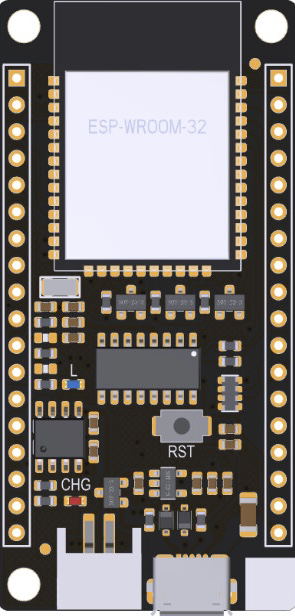
The ESP32, manufactured by Espressif, is a powerful microcontroller module with integrated Wi-Fi and Bluetooth capabilities. The specific model, WROOM-32D, is designed for high-performance IoT applications, offering robust wireless connectivity and versatile functionality. Its dual-core processor, low power consumption, and extensive peripheral support make it a popular choice for developers working on smart devices, home automation, wearables, and industrial IoT systems.
Explore Projects Built with ESP32


Explore Projects Built with ESP32
Common Applications and Use Cases
- IoT Devices: Smart home systems, environmental monitoring, and connected appliances.
- Wearables: Fitness trackers and health monitoring devices.
- Industrial Automation: Wireless sensor networks and machine-to-machine communication.
- Prototyping: Rapid development of wireless-enabled projects.
- Robotics: Remote-controlled robots and drones.
Technical Specifications
The ESP32 WROOM-32D module is packed with features that make it suitable for a wide range of applications. Below are its key technical details:
Key Technical Details
- Processor: Dual-core Xtensa® 32-bit LX6 microprocessor, up to 240 MHz.
- Wireless Connectivity:
- Wi-Fi: 802.11 b/g/n (2.4 GHz).
- Bluetooth: v4.2 BR/EDR and BLE.
- Flash Memory: 4 MB (external SPI flash).
- RAM: 520 KB SRAM.
- Operating Voltage: 3.0V to 3.6V.
- I/O Pins: 34 GPIO pins, configurable for various functions.
- ADC: 12-bit, up to 18 channels.
- DAC: 2 channels, 8-bit resolution.
- Communication Interfaces: UART, SPI, I2C, I2S, CAN, PWM.
- Power Consumption:
- Active mode: ~160 mA.
- Deep sleep mode: ~10 µA.
- Operating Temperature: -40°C to 85°C.
Pin Configuration and Descriptions
The ESP32 WROOM-32D module has 38 pins. Below is a table summarizing the key pin functions:
| Pin Number | Pin Name | Description |
|---|---|---|
| 1 | EN | Enable pin. Active high. Resets the chip when pulled low. |
| 2 | IO0 | GPIO0. Used to enter bootloader mode during programming. |
| 3 | IO2 | GPIO2. General-purpose I/O pin. |
| 4 | IO4 | GPIO4. General-purpose I/O pin. |
| 5 | IO5 | GPIO5. General-purpose I/O pin. |
| 6 | IO12 | GPIO12. Can be used as an ADC or touch sensor input. |
| 7 | IO13 | GPIO13. Can be used as an ADC or touch sensor input. |
| 8 | IO14 | GPIO14. Can be used as an ADC or touch sensor input. |
| 9 | IO15 | GPIO15. Can be used as an ADC or touch sensor input. |
| 10 | IO16 | GPIO16. General-purpose I/O pin. |
| 11 | IO17 | GPIO17. General-purpose I/O pin. |
| 12 | IO18 | GPIO18. SPI clock pin (SCK). |
| 13 | IO19 | GPIO19. SPI data pin (MISO). |
| 14 | IO21 | GPIO21. I2C data pin (SDA). |
| 15 | IO22 | GPIO22. I2C clock pin (SCL). |
| 16 | IO23 | GPIO23. SPI data pin (MOSI). |
| 17 | GND | Ground. |
| 18 | 3V3 | 3.3V power supply input. |
For a complete pinout, refer to the official Espressif datasheet.
Usage Instructions
The ESP32 WROOM-32D is versatile and can be used in a variety of circuits. Below are the steps and best practices for using the module effectively.
How to Use the ESP32 in a Circuit
- Power Supply: Provide a stable 3.3V power supply to the
3V3pin. Avoid exceeding 3.6V to prevent damage. - Boot Mode: To upload code, connect GPIO0 to GND and reset the module. After uploading, disconnect GPIO0 from GND.
- Programming: Use a USB-to-serial adapter to connect the ESP32 to your computer. Common baud rates are 115200 or 9600.
- Peripherals: Connect sensors, actuators, or other devices to the GPIO pins. Use appropriate pull-up or pull-down resistors if required.
- Wi-Fi and Bluetooth: Configure wireless settings in your code to enable connectivity.
Important Considerations and Best Practices
- Voltage Levels: Ensure all connected devices operate at 3.3V logic levels. Use level shifters if interfacing with 5V devices.
- Heat Management: The ESP32 can get warm during operation. Ensure proper ventilation or heat dissipation in your design.
- Antenna Placement: Avoid placing metal objects near the onboard antenna to maintain optimal wireless performance.
- Deep Sleep Mode: Use deep sleep mode to conserve power in battery-operated projects.
Example Code for Arduino UNO Integration
Below is an example of how to use the ESP32 with the Arduino IDE to connect to a Wi-Fi network:
#include <WiFi.h> // Include the Wi-Fi library

// Replace with your network credentials
const char* ssid = "Your_SSID";
const char* password = "Your_PASSWORD";

void setup() {
  Serial.begin(115200); // Initialize serial communication
  delay(1000); // Wait for serial monitor to initialize

  Serial.println("Connecting to Wi-Fi...");
  WiFi.begin(ssid, password); // Start Wi-Fi connection

  while (WiFi.status() != WL_CONNECTED) {
    delay(500); // Wait for connection
    Serial.print(".");
  }

  Serial.println("\nConnected to Wi-Fi!");
  Serial.print("IP Address: ");
  Serial.println(WiFi.localIP()); // Print the assigned IP address
}

void loop() {
  // Add your main code here
}
Troubleshooting and FAQs
Common Issues and Solutions
ESP32 Not Connecting to Wi-Fi:
- Ensure the SSID and password are correct.
- Check for interference or weak signal strength.
- Verify that the router supports 2.4 GHz Wi-Fi (ESP32 does not support 5 GHz).
Code Upload Fails:
- Ensure GPIO0 is connected to GND during programming.
- Check the USB-to-serial adapter connection and drivers.
- Use the correct COM port in the Arduino IDE.
Module Overheating:
- Reduce the operating frequency if possible.
- Ensure proper ventilation or add a heatsink.
Unstable Operation:
- Use a decoupling capacitor (e.g., 10 µF) near the power pins.
- Verify that the power supply provides sufficient current (at least 500 mA).
FAQs
Q: Can the ESP32 operate on battery power?
- A: Yes, the ESP32 can operate on battery power. Use a 3.7V LiPo battery with a voltage regulator to provide 3.3V.
Q: How do I reset the ESP32?
- A: Pull the EN pin low momentarily to reset the module.
Q: Can I use the ESP32 with 5V logic devices?
- A: No, the ESP32 operates at 3.3V logic levels. Use level shifters for 5V devices.
Q: Does the ESP32 support OTA updates?
- A: Yes, the ESP32 supports Over-The-Air (OTA) updates for firmware.
This documentation provides a comprehensive guide to using the ESP32 WROOM-32D module effectively. For further details, refer to the official Espressif documentation.