Cirkit Designer
Your all-in-one circuit design IDE
Home /
Component Documentation
How to Use gy_91: Examples, Pinouts, and Specs
Introduction
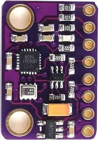
The GY-91 is a compact sensor module manufactured by InvenSense, combining the MPU9250 (a 9-axis motion tracking device) and the BMP280 (a precision barometric pressure sensor). This module integrates a 3-axis accelerometer, 3-axis gyroscope, 3-axis magnetometer, and a barometric pressure sensor, making it ideal for applications requiring motion tracking, orientation sensing, and altitude measurement.
Explore Projects Built with gy_91
Arduino-Based Water Quality Monitoring System with SIM900A and Multiple Sensors
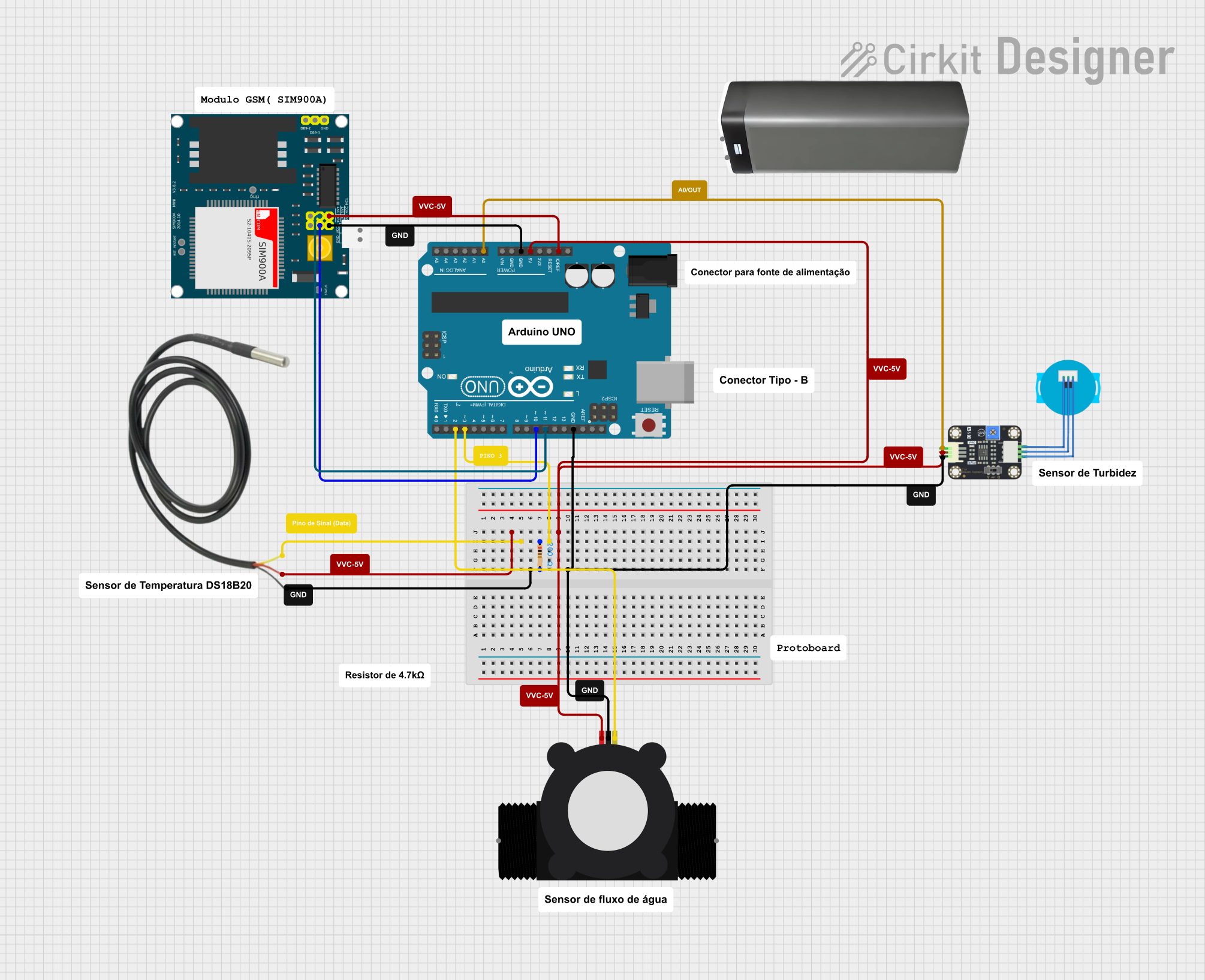
This circuit is a water quality monitoring system that uses an Arduino UNO to collect data from a YF-S201 water flow meter, a turbidity sensor, and a temperature sensor. The collected data is then transmitted via a SIM900A GSM module to a remote server or user through SMS. The system measures water flow rate, temperature, and turbidity, and sends periodic updates.
Arduino Leonardo Soldier Tracking System with GPS, GSM, and Environmental Sensors
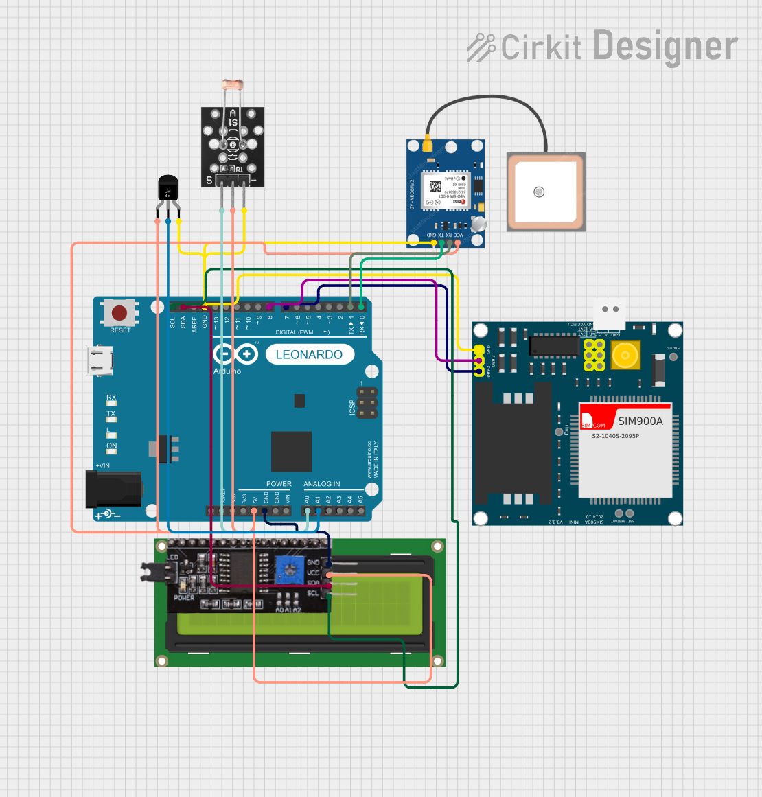
This circuit is designed for a soldier tracking system that monitors environmental conditions and location. It uses an Arduino Leonardo to interface with a GPS module for location tracking, a SIM900A GSM module for SMS communication, a temperature sensor (LM35) for ambient temperature measurement, and an LDR photoresistor for light intensity which could be used as a proxy for heartbeat monitoring. The system can send the soldier's location, temperature, and heartbeat data via SMS and displays status information on an LCD screen connected via an I2C module.
Arduino Mega 2560-Based Smart Lock System with Servo Control and GSM Connectivity
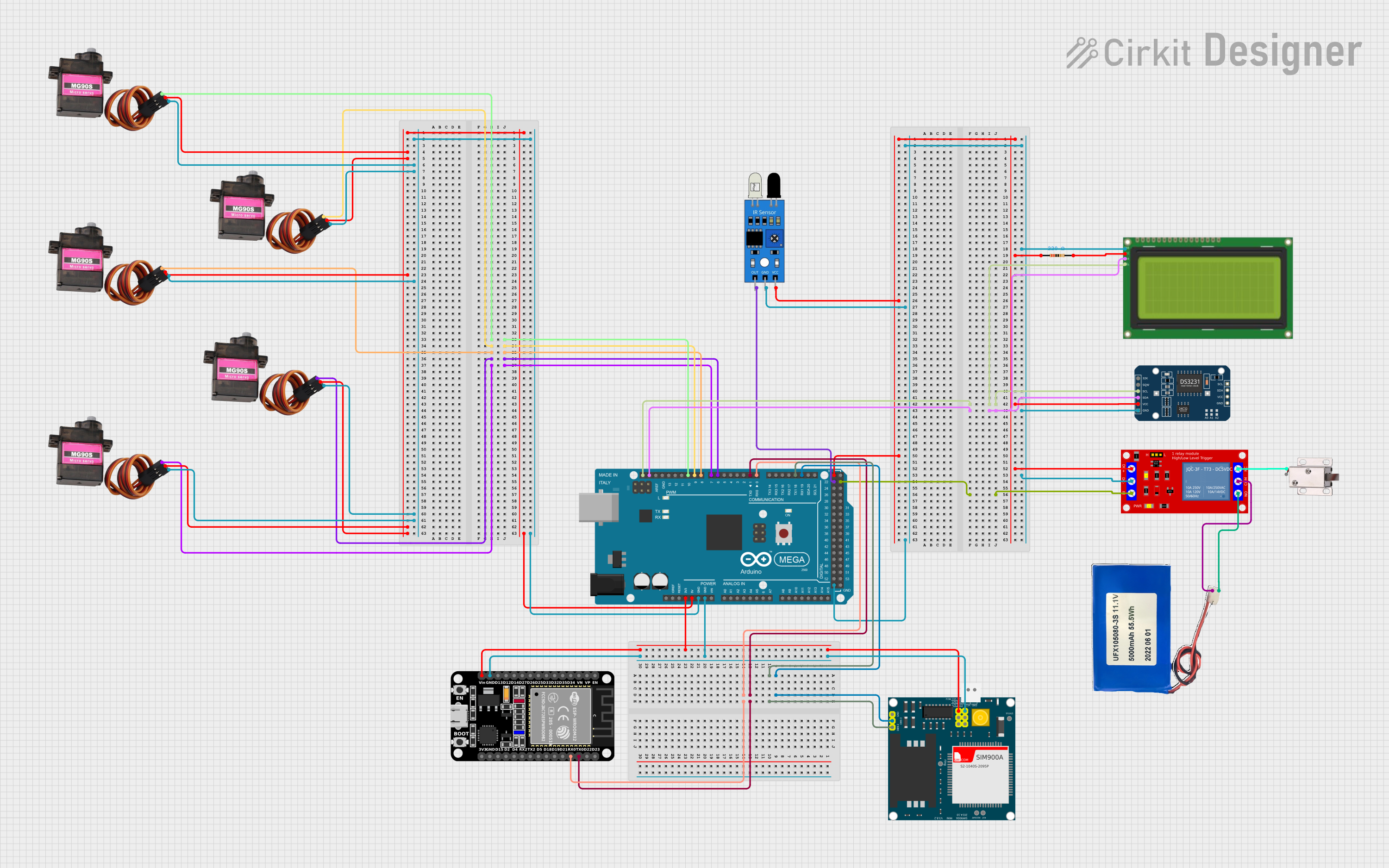
This circuit is a control system utilizing an Arduino Mega 2560 to manage multiple MG90S servos, an LCD display, a DS3231 RTC module, a SIM900A GSM module, and an ESP32 for communication. It also includes a relay module to control a 12V solenoid lock, an IR sensor for input, and a Li-ion battery for power supply.
ADXL335 Accelerometer Data Visualization with Oscilloscope

This circuit connects an AITrip ADXL335 GY-61 accelerometer to an oscilloscope for signal visualization and a 3xAA battery pack for power. The accelerometer's Z-axis output is directly monitored on the oscilloscope, allowing for real-time observation of acceleration changes along that axis. The circuit is likely used for educational or testing purposes to demonstrate how the accelerometer responds to motion.
Explore Projects Built with gy_91
Arduino-Based Water Quality Monitoring System with SIM900A and Multiple Sensors
This circuit is a water quality monitoring system that uses an Arduino UNO to collect data from a YF-S201 water flow meter, a turbidity sensor, and a temperature sensor. The collected data is then transmitted via a SIM900A GSM module to a remote server or user through SMS. The system measures water flow rate, temperature, and turbidity, and sends periodic updates.
Arduino Leonardo Soldier Tracking System with GPS, GSM, and Environmental Sensors
This circuit is designed for a soldier tracking system that monitors environmental conditions and location. It uses an Arduino Leonardo to interface with a GPS module for location tracking, a SIM900A GSM module for SMS communication, a temperature sensor (LM35) for ambient temperature measurement, and an LDR photoresistor for light intensity which could be used as a proxy for heartbeat monitoring. The system can send the soldier's location, temperature, and heartbeat data via SMS and displays status information on an LCD screen connected via an I2C module.
Arduino Mega 2560-Based Smart Lock System with Servo Control and GSM Connectivity
This circuit is a control system utilizing an Arduino Mega 2560 to manage multiple MG90S servos, an LCD display, a DS3231 RTC module, a SIM900A GSM module, and an ESP32 for communication. It also includes a relay module to control a 12V solenoid lock, an IR sensor for input, and a Li-ion battery for power supply.
ADXL335 Accelerometer Data Visualization with Oscilloscope
This circuit connects an AITrip ADXL335 GY-61 accelerometer to an oscilloscope for signal visualization and a 3xAA battery pack for power. The accelerometer's Z-axis output is directly monitored on the oscilloscope, allowing for real-time observation of acceleration changes along that axis. The circuit is likely used for educational or testing purposes to demonstrate how the accelerometer responds to motion.
Common Applications
- Robotics and autonomous vehicles
- Drones and UAVs for stabilization and navigation
- Mobile devices for motion and orientation sensing
- Wearable devices and fitness trackers
- Weather stations and altitude measurement systems
Technical Specifications
Key Technical Details
| Parameter | Value |
|---|---|
| Manufacturer | InvenSense |
| Part ID | MPU9250 + BMP280 |
| Operating Voltage | 3.3V - 5V |
| Communication Interface | I2C (default) and SPI |
| Accelerometer Range | ±2g, ±4g, ±8g, ±16g |
| Gyroscope Range | ±250, ±500, ±1000, ±2000 °/s |
| Magnetometer Range | ±4800 µT |
| Barometric Pressure Range | 300 hPa to 1100 hPa |
| Operating Temperature | -40°C to +85°C |
| Dimensions | 15mm x 10mm x 2mm |
Pin Configuration and Descriptions
| Pin Name | Description |
|---|---|
| VCC | Power supply input (3.3V to 5V). |
| GND | Ground connection. |
| SCL | I2C clock line (or SPI clock line in SPI mode). |
| SDA | I2C data line (or SPI data line in SPI mode). |
| CS | Chip select for SPI communication (active low). |
| INT | Interrupt pin for motion detection or data-ready signals. |
| NCS | Not connected (can be left floating or grounded, depending on the module). |
Usage Instructions
How to Use the GY-91 in a Circuit
- Power the Module: Connect the VCC pin to a 3.3V or 5V power source and GND to ground.
- Connect Communication Lines:
- For I2C: Connect the SCL and SDA pins to the corresponding I2C pins on your microcontroller.
- For SPI: Connect the SCL, SDA, and CS pins to the SPI clock, data, and chip select pins, respectively.
- Pull-Up Resistors: Ensure pull-up resistors (typically 4.7kΩ) are present on the I2C lines if not already included on the module.
- Initialize the Sensor: Use appropriate libraries or write custom code to initialize and configure the MPU9250 and BMP280.
Important Considerations and Best Practices
- Voltage Compatibility: Ensure your microcontroller's I2C or SPI pins are compatible with the GY-91's voltage levels (3.3V or 5V).
- Magnetometer Calibration: Perform a magnetometer calibration to ensure accurate heading measurements.
- Mounting Orientation: Mount the module securely and in the correct orientation for accurate motion and orientation sensing.
- Noise Filtering: Use software filters to reduce noise in accelerometer and gyroscope readings.
Example Code for Arduino UNO
Below is an example of how to interface the GY-91 with an Arduino UNO using the I2C protocol. This code uses the Adafruit_Sensor and Adafruit_BMP280 libraries for the BMP280 and the MPU9250 library for the MPU9250.
#include <Wire.h>
#include <Adafruit_Sensor.h>
#include <Adafruit_BMP280.h>
#include <MPU9250.h>

// Create instances for the sensors
Adafruit_BMP280 bmp; // BMP280 instance
MPU9250 mpu(Wire, 0x68); // MPU9250 instance with I2C address 0x68

void setup() {
  Serial.begin(9600);
  Wire.begin();

  // Initialize BMP280
  if (!bmp.begin(0x76)) { // Default I2C address for BMP280 is 0x76
    Serial.println("BMP280 initialization failed!");
    while (1);
  }
  Serial.println("BMP280 initialized successfully.");

  // Initialize MPU9250
  if (mpu.begin() != 0) {
    Serial.println("MPU9250 initialization failed!");
    while (1);
  }
  Serial.println("MPU9250 initialized successfully.");
}

void loop() {
  // Read BMP280 data
  float temperature = bmp.readTemperature();
  float pressure = bmp.readPressure();
  float altitude = bmp.readAltitude(1013.25); // Sea level pressure in hPa

  // Read MPU9250 data
  mpu.readSensor();
  float accelX = mpu.getAccelX_mss();
  float accelY = mpu.getAccelY_mss();
  float accelZ = mpu.getAccelZ_mss();
  float gyroX = mpu.getGyroX_rads();
  float gyroY = mpu.getGyroY_rads();
  float gyroZ = mpu.getGyroZ_rads();
  float magX = mpu.getMagX_uT();
  float magY = mpu.getMagY_uT();
  float magZ = mpu.getMagZ_uT();

  // Print sensor data
  Serial.print("Temperature: "); Serial.print(temperature); Serial.println(" °C");
  Serial.print("Pressure: "); Serial.print(pressure); Serial.println(" Pa");
  Serial.print("Altitude: "); Serial.print(altitude); Serial.println(" m");
  Serial.print("Accel (X, Y, Z): ");
  Serial.print(accelX); Serial.print(", ");
  Serial.print(accelY); Serial.print(", ");
  Serial.println(accelZ);
  Serial.print("Gyro (X, Y, Z): ");
  Serial.print(gyroX); Serial.print(", ");
  Serial.print(gyroY); Serial.print(", ");
  Serial.println(gyroZ);
  Serial.print("Mag (X, Y, Z): ");
  Serial.print(magX); Serial.print(", ");
  Serial.print(magY); Serial.print(", ");
  Serial.println(magZ);

  delay(1000); // Wait 1 second before the next reading
}
Troubleshooting and FAQs
Common Issues
Sensor Not Detected:
- Ensure the I2C or SPI connections are correct.
- Verify the I2C address (default is 0x68 for MPU9250 and 0x76 for BMP280).
- Check for proper power supply (3.3V or 5V).
Inaccurate Readings:
- Perform calibration for the accelerometer, gyroscope, and magnetometer.
- Ensure the module is mounted securely and free from vibrations.
Communication Errors:
- Check for loose or incorrect wiring.
- Ensure pull-up resistors are present on the I2C lines.
Solutions and Tips
- Use a logic level shifter if your microcontroller operates at 5V and the GY-91 is running at 3.3V.
- For better accuracy, use software libraries that support sensor fusion algorithms (e.g., Madgwick or Mahony filters).
- Avoid placing the module near magnetic or electrical interference sources.