Cirkit Designer Logo
Cirkit Designer
Your all-in-one circuit design IDE
Home / 
Component Documentation

How to Use LED Yellow: Examples, Pinouts, and Specs

Image of LED Yellow
Cirkit Designer LogoDesign with LED Yellow in Cirkit Designer

Introduction

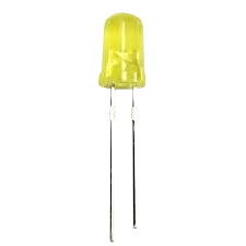
A yellow light-emitting diode (LED) is a semiconductor device that emits yellow light when an electric current flows through it. It is widely used in electronic circuits for visual indicators, status displays, and decorative lighting. Yellow LEDs are valued for their low power consumption, long lifespan, and high efficiency.

Explore Projects Built with LED Yellow

Use Cirkit Designer to design, explore, and prototype these projects online. Some projects support real-time simulation. Click "Open Project" to start designing instantly!
Raspberry Pi 4B Controlled Multi-Color LED Indicator
Image of Task1-osama: A project utilizing LED Yellow in a practical application
This circuit consists of three LEDs (yellow, green, and red) each with a corresponding 220 Ohm resistor in series. The anodes of the LEDs are connected to their respective resistors, while the cathodes are likely intended to be driven by a Raspberry Pi 4B, as the resistors' other ends are connected to the Pi's 3.3V and GND pins. Without specific code, the functionality of the Raspberry Pi in this circuit cannot be determined, but it is likely used to control the LEDs.
Cirkit Designer LogoOpen Project in Cirkit Designer
Arduino Mega 2560 Controlled Traffic Light System with TM1637 Displays
Image of Traffic circuit diagram : A project utilizing LED Yellow in a practical application
This circuit is designed to simulate a set of traffic lights using an Arduino Mega 2560 microcontroller to control multiple sets of red, yellow, and green LEDs. Each LED color is connected to a specific PWM-capable digital pin on the Arduino, allowing for individual control. The circuit also includes multiple TM1637 7-segment display modules, each connected to the Arduino via I2C communication, to display countdown timers corresponding to the traffic light states.
Cirkit Designer LogoOpen Project in Cirkit Designer
Battery-Powered LED Indicator Circuit with Rocker Switches
Image of Intern 1: A project utilizing LED Yellow in a practical application
This circuit consists of three LEDs (red, green, and yellow) each connected in series with a 1k Ohm resistor and controlled by individual rocker switches. The LEDs share a common ground with a 9V battery, and the switches are connected to the positive terminal of the battery, allowing each LED to be turned on or off independently.
Cirkit Designer LogoOpen Project in Cirkit Designer
Wi-Fi Controlled LED Indicator using ESP8266 NodeMCU
Image of esp8266 pin : A project utilizing LED Yellow in a practical application
This circuit uses an ESP8266 NodeMCU microcontroller to control two LEDs, one green and one yellow. The green LED is connected to pin D1, and the yellow LED is connected to pin D2, with both LEDs sharing a common ground with the microcontroller.
Cirkit Designer LogoOpen Project in Cirkit Designer

Explore Projects Built with LED Yellow

Use Cirkit Designer to design, explore, and prototype these projects online. Some projects support real-time simulation. Click "Open Project" to start designing instantly!
Image of Task1-osama: A project utilizing LED Yellow in a practical application
Raspberry Pi 4B Controlled Multi-Color LED Indicator
This circuit consists of three LEDs (yellow, green, and red) each with a corresponding 220 Ohm resistor in series. The anodes of the LEDs are connected to their respective resistors, while the cathodes are likely intended to be driven by a Raspberry Pi 4B, as the resistors' other ends are connected to the Pi's 3.3V and GND pins. Without specific code, the functionality of the Raspberry Pi in this circuit cannot be determined, but it is likely used to control the LEDs.
Cirkit Designer LogoOpen Project in Cirkit Designer
Image of Traffic circuit diagram : A project utilizing LED Yellow in a practical application
Arduino Mega 2560 Controlled Traffic Light System with TM1637 Displays
This circuit is designed to simulate a set of traffic lights using an Arduino Mega 2560 microcontroller to control multiple sets of red, yellow, and green LEDs. Each LED color is connected to a specific PWM-capable digital pin on the Arduino, allowing for individual control. The circuit also includes multiple TM1637 7-segment display modules, each connected to the Arduino via I2C communication, to display countdown timers corresponding to the traffic light states.
Cirkit Designer LogoOpen Project in Cirkit Designer
Image of Intern 1: A project utilizing LED Yellow in a practical application
Battery-Powered LED Indicator Circuit with Rocker Switches
This circuit consists of three LEDs (red, green, and yellow) each connected in series with a 1k Ohm resistor and controlled by individual rocker switches. The LEDs share a common ground with a 9V battery, and the switches are connected to the positive terminal of the battery, allowing each LED to be turned on or off independently.
Cirkit Designer LogoOpen Project in Cirkit Designer
Image of esp8266 pin : A project utilizing LED Yellow in a practical application
Wi-Fi Controlled LED Indicator using ESP8266 NodeMCU
This circuit uses an ESP8266 NodeMCU microcontroller to control two LEDs, one green and one yellow. The green LED is connected to pin D1, and the yellow LED is connected to pin D2, with both LEDs sharing a common ground with the microcontroller.
Cirkit Designer LogoOpen Project in Cirkit Designer

Common Applications

  • Power and status indicators in electronic devices
  • Signal lights in control panels
  • Decorative and ambient lighting
  • Displays in digital clocks, calculators, and other devices
  • Educational and hobbyist projects

Technical Specifications

Below are the key technical details for a standard yellow LED:

Parameter Value
Forward Voltage (Vf) 2.0V - 2.2V
Forward Current (If) 20mA (typical)
Maximum Current (Imax) 30mA
Wavelength 585nm - 595nm (yellow light)
Viewing Angle 20° - 30°
Power Dissipation 60mW (maximum)
Operating Temperature -40°C to +85°C

Pin Configuration

Yellow LEDs typically have two pins: the anode (positive) and the cathode (negative). The longer pin is the anode, and the shorter pin is the cathode. The cathode is also marked by a flat edge on the LED casing.

Pin Name Description
Anode Connects to the positive terminal of the power supply.
Cathode Connects to the negative terminal or ground.

Usage Instructions

How to Use the Yellow LED in a Circuit

  1. Determine the Resistor Value: To prevent damage to the LED, a current-limiting resistor must be used in series with the LED. Use Ohm's Law to calculate the resistor value: [ R = \frac{V_{supply} - V_f}{I_f} ]

    • (V_{supply}): Supply voltage
    • (V_f): Forward voltage of the LED (2.0V - 2.2V)
    • (I_f): Desired forward current (typically 20mA)

    For example, if (V_{supply} = 5V): [ R = \frac{5V - 2.1V}{0.02A} = 145\Omega ] Use a standard resistor value of 150Ω.

  2. Connect the LED:

    • Connect the anode to the positive terminal of the power supply through the resistor.
    • Connect the cathode to the ground.
  3. Test the Circuit: Apply power to the circuit. The LED should emit yellow light.

Important Considerations

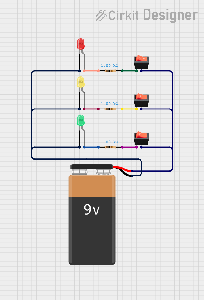
  • Polarity: LEDs are polarized components. Reversing the polarity may damage the LED.
  • Current Limiting: Always use a resistor to limit the current through the LED.
  • Brightness Control: Use a pulse-width modulation (PWM) signal to adjust the brightness of the LED.

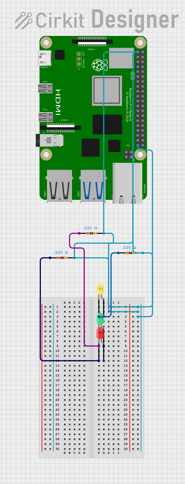
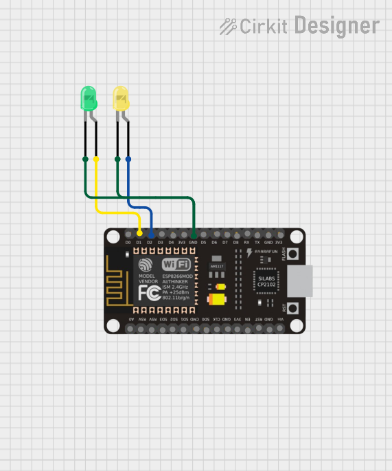
Example: Connecting a Yellow LED to an Arduino UNO

Below is an example of how to connect and control a yellow LED using an Arduino UNO:

Circuit Setup

  • Connect the anode of the LED to digital pin 9 on the Arduino through a 150Ω resistor.
  • Connect the cathode of the LED to the ground (GND) pin on the Arduino.

Arduino Code

// Define the pin connected to the LED
const int ledPin = 9;

void setup() {
  // Set the LED pin as an output
  pinMode(ledPin, OUTPUT);
}

void loop() {
  // Turn the LED on
  digitalWrite(ledPin, HIGH);
  delay(1000); // Wait for 1 second

  // Turn the LED off
  digitalWrite(ledPin, LOW);
  delay(1000); // Wait for 1 second
}

Troubleshooting and FAQs

Common Issues

  1. LED Does Not Light Up:

    • Cause: Incorrect polarity.

    • Solution: Ensure the anode is connected to the positive terminal and the cathode to ground.

    • Cause: No current-limiting resistor.

    • Solution: Add a resistor in series with the LED to limit the current.

  2. LED is Dim:

    • Cause: Resistor value is too high.
    • Solution: Recalculate the resistor value and use a lower resistance.
  3. LED Burns Out:

    • Cause: Excessive current.
    • Solution: Use a resistor with the correct value to limit the current to 20mA.
  4. Flickering LED:

    • Cause: Unstable power supply or loose connections.
    • Solution: Check the power supply and ensure all connections are secure.

FAQs

Q: Can I connect the LED directly to a 3.3V or 5V power supply?
A: No, you must use a current-limiting resistor to prevent excessive current from damaging the LED.

Q: How do I control the brightness of the LED?
A: Use a PWM signal from a microcontroller (e.g., Arduino) to adjust the brightness.

Q: Can I use the yellow LED in an AC circuit?
A: LEDs are designed for DC circuits. To use them in AC circuits, you must add a rectifier and a current-limiting resistor.

Q: What happens if I reverse the polarity of the LED?
A: The LED will not light up, and prolonged reverse polarity may damage the LED. Always connect the anode to the positive terminal and the cathode to ground.