How to Use RJ45 Cat6 T568A Connectors (Дзеркально): Examples, Pinouts, and Specs
Introduction
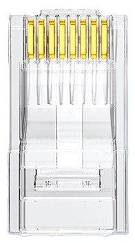
RJ45 Cat6 T568A connectors are used for terminating Ethernet cables, providing a reliable connection for networking applications. These connectors are designed to support high-speed data transmission, making them ideal for use in modern networking environments. The T568A wiring standard ensures proper pin configuration, which is critical for maintaining signal integrity and minimizing crosstalk. The term "Дзеркально" (mirror) refers to the mirrored arrangement of the wiring when viewed from the opposite side.
Explore Projects Built with RJ45 Cat6 T568A Connectors (Дзеркально)


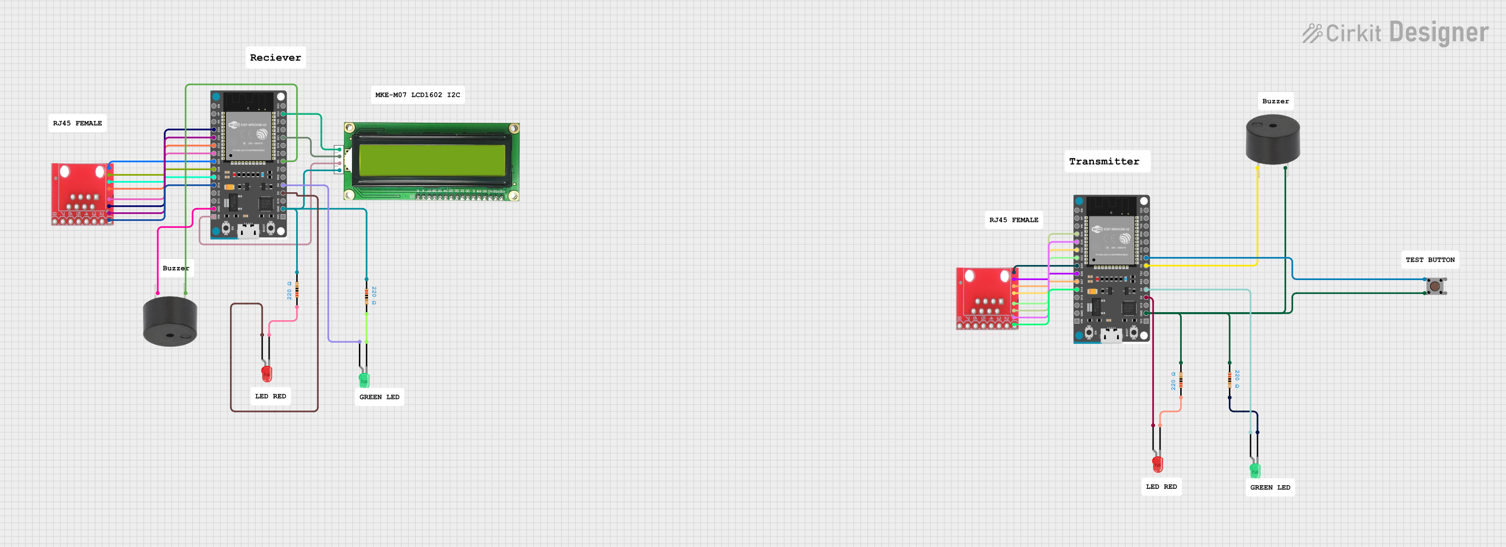

Explore Projects Built with RJ45 Cat6 T568A Connectors (Дзеркально)
Common Applications and Use Cases
- Ethernet networking for homes, offices, and data centers
- Termination of Cat6 cables for high-speed internet and LAN connections
- Use in patch panels, keystone jacks, and wall plates
- Applications requiring compliance with the T568A wiring standard
Technical Specifications
Key Technical Details
- Connector Type: RJ45 (8P8C)
- Cable Compatibility: Cat6 (unshielded or shielded twisted pair)
- Wiring Standard: T568A
- Supported Speeds: Up to 10 Gbps (when used with Cat6 cables)
- Material: Gold-plated contacts for improved conductivity and corrosion resistance
- Operating Temperature: -40°C to 85°C
- Durability: Rated for 750+ mating cycles
Pin Configuration and Descriptions
The T568A wiring standard specifies the following pinout for the RJ45 connector:
| Pin Number | Wire Color (T568A Standard) | Signal Description |
|---|---|---|
| 1 | White/Green | Transmit Data + (TX+) |
| 2 | Green | Transmit Data - (TX-) |
| 3 | White/Orange | Receive Data + (RX+) |
| 4 | Blue | Unused (Power over Ethernet - Positive) |
| 5 | White/Blue | Unused (Power over Ethernet - Positive) |
| 6 | Orange | Receive Data - (RX-) |
| 7 | White/Brown | Unused (Power over Ethernet - Negative) |
| 8 | Brown | Unused (Power over Ethernet - Negative) |
Usage Instructions
How to Use the Component in a Circuit
- Prepare the Cable: Strip approximately 1 inch of the outer jacket from the Cat6 cable, exposing the twisted pairs.
- Untwist and Arrange Wires: Untwist the wire pairs and arrange them according to the T568A wiring standard.
- Trim the Wires: Cut the wires to an even length, leaving about 0.5 inches exposed.
- Insert into the Connector: Insert the wires into the RJ45 connector, ensuring each wire is fully seated in its respective slot.
- Crimp the Connector: Use an RJ45 crimping tool to secure the connector to the cable. Ensure the gold contacts pierce the wire insulation for a solid connection.
- Test the Connection: Use a cable tester to verify the pinout and continuity.
Important Considerations and Best Practices
- Always use high-quality Cat6 cables and connectors to ensure optimal performance.
- Avoid excessive untwisting of wire pairs, as this can degrade signal quality.
- Ensure the wires are arranged correctly according to the T568A standard to prevent connectivity issues.
- Use a proper crimping tool to avoid damaging the connector or cable.
- If using Power over Ethernet (PoE), ensure the connector and cable are rated for the required power level.
Example: Connecting to an Arduino UNO
While RJ45 connectors are not directly compatible with an Arduino UNO, you can use an Ethernet shield to interface with the Arduino. Below is an example of Arduino code for using an Ethernet shield with an RJ45 Cat6 T568A connector:
#include <SPI.h>
#include <Ethernet.h>

// MAC address and IP address for the Ethernet shield
byte mac[] = { 0xDE, 0xAD, 0xBE, 0xEF, 0xFE, 0xED };
IPAddress ip(192, 168, 1, 177);

// Initialize the Ethernet server on port 80
EthernetServer server(80);

void setup() {
  // Start the Ethernet connection
  Ethernet.begin(mac, ip);

  // Start the server
  server.begin();
  Serial.begin(9600);
  Serial.println("Server is ready at IP: ");
  Serial.println(Ethernet.localIP());
}

void loop() {
  // Listen for incoming clients
  EthernetClient client = server.available();
  if (client) {
    Serial.println("New client connected");
    while (client.connected()) {
      if (client.available()) {
        char c = client.read();
        Serial.write(c); // Echo the received data to the Serial Monitor
      }
    }
    client.stop();
    Serial.println("Client disconnected");
  }
}
Troubleshooting and FAQs
Common Issues Users Might Face
- Incorrect Wiring Order: If the wires are not arranged according to the T568A standard, the connection will fail.
- Solution: Double-check the wiring order before crimping the connector.
- Poor Crimping: If the connector is not crimped properly, it may result in intermittent connections.
- Solution: Use a high-quality crimping tool and ensure the gold contacts pierce the wire insulation.
- Signal Loss or Crosstalk: Excessive untwisting of wire pairs can degrade signal quality.
- Solution: Minimize untwisting and maintain the twist as close to the connector as possible.
- Cable Tester Fails: If the cable tester indicates a fault, it could be due to a misaligned wire or a damaged connector.
- Solution: Re-terminate the cable, ensuring proper alignment and crimping.
Solutions and Tips for Troubleshooting
- Use a cable tester to quickly identify wiring faults or continuity issues.
- Inspect the connector for visible damage or misaligned wires.
- Ensure the cable jacket is securely clamped in the connector to prevent strain on the wires.
- If using shielded Cat6 cables, ensure the shield is properly grounded to reduce electromagnetic interference.
By following these guidelines, you can ensure reliable and high-performance connections with RJ45 Cat6 T568A connectors.