Cirkit Designer Logo
Cirkit Designer
Your all-in-one circuit design IDE
Home / 
Component Documentation

How to Use Tinkerboard S: Examples, Pinouts, and Specs

Image of Tinkerboard S
Cirkit Designer LogoDesign with Tinkerboard S in Cirkit Designer

Introduction

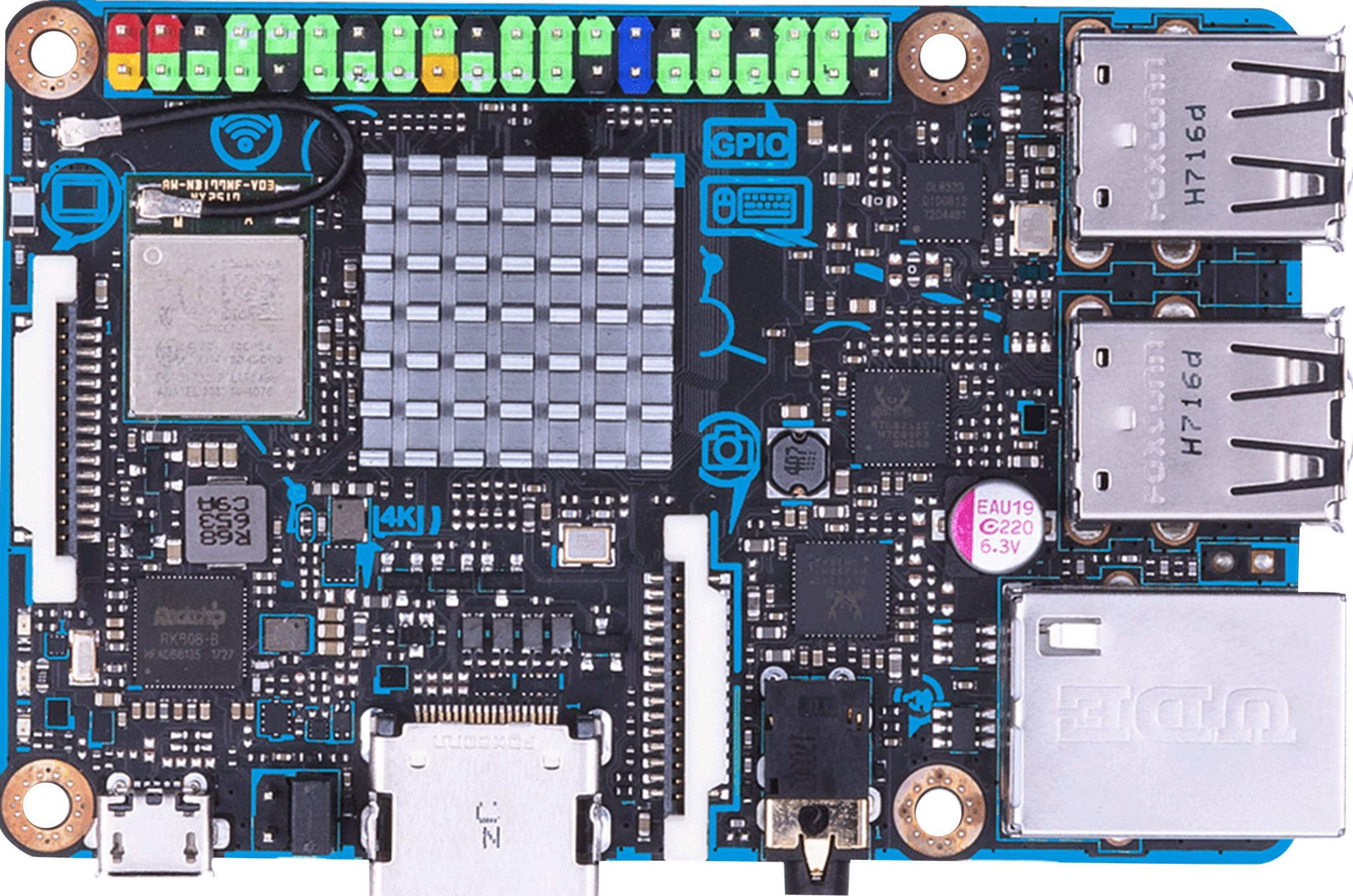
The ASUS Tinkerboard S is a powerful single-board computer that offers enhanced performance and robustness for hobbyists, makers, and professionals alike. It is equipped with a quad-core ARM Cortex-A17 CPU, making it suitable for a variety of applications ranging from DIY projects to Internet of Things (IoT) implementations. Its compatibility with various operating systems and the inclusion of onboard storage make it a versatile choice for projects that require a compact yet powerful computing solution.

Explore Projects Built with Tinkerboard S

Use Cirkit Designer to design, explore, and prototype these projects online. Some projects support real-time simulation. Click "Open Project" to start designing instantly!
Beelink Mini S12 N95 and Arduino UNO Based Fingerprint Authentication System with ESP32 CAM
Image of design 3: A project utilizing Tinkerboard S in a practical application
This circuit features a Beelink MINI S12 N95 computer connected to a 7-inch display via HDMI for video output and two USB connections for power and touch screen functionality. An Arduino UNO is interfaced with a fingerprint scanner for biometric input. The Beelink MINI S12 N95 is powered by a PC power supply, which in turn is connected to a 240V power source. Additionally, an ESP32 CAM module is powered and programmed via a USB plug and an FTDI programmer, respectively, for wireless camera capabilities.
Cirkit Designer LogoOpen Project in Cirkit Designer
ESP32-S3 Based Vibration Detection System with TFT Display and Power Backup
Image of IOT Thesis: A project utilizing Tinkerboard S in a practical application
This circuit features an ESP32-S3 microcontroller connected to various peripherals including an ADXL355 accelerometer, an SW-420 vibration sensor, a buzzer module, and an ILI9341 TFT display. The ESP32-S3 manages sensor inputs and provides output to the display and buzzer. Power management is handled by a 12V to 5V step-down converter, and a UPS ensures uninterrupted power supply, with a rocker switch to control the power flow.
Cirkit Designer LogoOpen Project in Cirkit Designer
I2C-Controlled OLED Display with External EEPROM and Interactive Pushbuttons
Image of godmode: A project utilizing Tinkerboard S in a practical application
This is a microcontroller-based interactive device featuring a Wemos D1 Mini, an OLED display, external EEPROM, and an I/O expander. It includes user input buttons and status LEDs, with potential MIDI interface capabilities.
Cirkit Designer LogoOpen Project in Cirkit Designer
T-Beam with I2C OLED Display Interface
Image of MQTT_Node: A project utilizing Tinkerboard S in a practical application
This circuit connects a T-Beam microcontroller board with an OLED 128x64 I2C Monochrome Display. The T-Beam's I2C pins (SDA and SCL) are wired to the corresponding SDA and SCK pins on the OLED display, allowing for communication between the microcontroller and the display. Power and ground connections are also established, with the display's VDD connected to the T-Beam's 3V3 output, and GND to GND, to complete the power circuit for the display.
Cirkit Designer LogoOpen Project in Cirkit Designer

Explore Projects Built with Tinkerboard S

Use Cirkit Designer to design, explore, and prototype these projects online. Some projects support real-time simulation. Click "Open Project" to start designing instantly!
Image of design 3: A project utilizing Tinkerboard S in a practical application
Beelink Mini S12 N95 and Arduino UNO Based Fingerprint Authentication System with ESP32 CAM
This circuit features a Beelink MINI S12 N95 computer connected to a 7-inch display via HDMI for video output and two USB connections for power and touch screen functionality. An Arduino UNO is interfaced with a fingerprint scanner for biometric input. The Beelink MINI S12 N95 is powered by a PC power supply, which in turn is connected to a 240V power source. Additionally, an ESP32 CAM module is powered and programmed via a USB plug and an FTDI programmer, respectively, for wireless camera capabilities.
Cirkit Designer LogoOpen Project in Cirkit Designer
Image of IOT Thesis: A project utilizing Tinkerboard S in a practical application
ESP32-S3 Based Vibration Detection System with TFT Display and Power Backup
This circuit features an ESP32-S3 microcontroller connected to various peripherals including an ADXL355 accelerometer, an SW-420 vibration sensor, a buzzer module, and an ILI9341 TFT display. The ESP32-S3 manages sensor inputs and provides output to the display and buzzer. Power management is handled by a 12V to 5V step-down converter, and a UPS ensures uninterrupted power supply, with a rocker switch to control the power flow.
Cirkit Designer LogoOpen Project in Cirkit Designer
Image of godmode: A project utilizing Tinkerboard S in a practical application
I2C-Controlled OLED Display with External EEPROM and Interactive Pushbuttons
This is a microcontroller-based interactive device featuring a Wemos D1 Mini, an OLED display, external EEPROM, and an I/O expander. It includes user input buttons and status LEDs, with potential MIDI interface capabilities.
Cirkit Designer LogoOpen Project in Cirkit Designer
Image of MQTT_Node: A project utilizing Tinkerboard S in a practical application
T-Beam with I2C OLED Display Interface
This circuit connects a T-Beam microcontroller board with an OLED 128x64 I2C Monochrome Display. The T-Beam's I2C pins (SDA and SCL) are wired to the corresponding SDA and SCK pins on the OLED display, allowing for communication between the microcontroller and the display. Power and ground connections are also established, with the display's VDD connected to the T-Beam's 3V3 output, and GND to GND, to complete the power circuit for the display.
Cirkit Designer LogoOpen Project in Cirkit Designer

Common Applications and Use Cases

  • Home automation systems
  • Media centers
  • Educational platforms for coding and electronics
  • Prototyping IoT devices
  • Embedded computing projects
  • Digital signage and kiosks

Technical Specifications

Key Technical Details

  • CPU: Rockchip RK3288, Quad-core ARM Cortex-A17
  • GPU: ARM Mali-T764
  • RAM: 2GB LPDDR3
  • Storage: 16GB eMMC, Micro SD(TF) card slot
  • Connectivity: Gigabit Ethernet, Wi-Fi 802.11 b/g/n, Bluetooth 4.0 + EDR
  • USB Ports: 4 x USB 2.0
  • Video Output: HDMI 2.0 (up to 4K resolution)
  • Audio: 3.5mm Audio Jack, HD Codec that supports up to 24-bit/192kHz audio
  • GPIO: 40-pin header: up to 28 x GPIO pins, up to 2 x SPI bus, up to 2 x I2C bus, up to 4 x UART, up to 2 x PWM, up to 1 x PCM/I2S, up to 1 x SPDIF TX, up to 6 x ADC
  • Power Supply: 5V/2-3A via Micro USB or GPIO

Pin Configuration and Descriptions

Pin Number Description Pin Number Description
1 3.3V Power 2 5V Power
3 GPIO2 (I2C SDA) 4 5V Power
5 GPIO3 (I2C SCL) 6 Ground
... ... ... ...
39 Ground 40 GPIO21 (PWM0)

Note: The above table is a partial representation. Refer to the Tinkerboard S GPIO pinout diagram for the complete details.

Usage Instructions

How to Use the Tinkerboard S in a Circuit

  1. Powering the Board: Connect a 5V/2-3A power supply to the Micro USB port or via the GPIO pins.
  2. Setting Up Storage: Use the onboard 16GB eMMC or insert a Micro SD card with a compatible OS image.
  3. Connecting Peripherals: Attach necessary peripherals such as keyboard, mouse, and display via USB ports and HDMI output.
  4. Programming: Access the board through SSH or a direct user interface to program and control the Tinkerboard S.

Important Considerations and Best Practices

  • Always handle the board with care to avoid static discharge or physical damage.
  • Ensure the power supply is adequate and stable.
  • Use heat sinks and proper ventilation if running CPU/GPU intensive tasks.
  • Regularly update the operating system and software to maintain security and performance.

Troubleshooting and FAQs

Common Issues

  • Board Does Not Power On: Check the power supply and cable connections. Ensure the power source meets the required specifications.
  • No Video Output: Verify that the HDMI cable is properly connected and the display is powered on. Check the display settings in the OS.
  • Inaccessible via Network: Ensure the Ethernet cable is connected and the network is functioning. Check Wi-Fi settings if using a wireless connection.

Solutions and Tips for Troubleshooting

  • If the board is unresponsive, attempt to power cycle by disconnecting and reconnecting the power supply.
  • For network issues, try connecting to a different port on the router or use a different Wi-Fi network.
  • Consult the Tinkerboard S forums and community for support on specific issues.

FAQs

Q: Can the Tinkerboard S run Android or Linux? A: Yes, the Tinkerboard S supports various versions of Android and Linux distributions that are compatible with the ARM architecture.

Q: Is the GPIO pinout compatible with the Raspberry Pi? A: While the Tinkerboard S has a similar 40-pin GPIO header, the pinout and functionality may differ. Always refer to the Tinkerboard S documentation for accurate pin assignments.

Q: Can I use the Tinkerboard S for commercial products? A: Yes, the Tinkerboard S is suitable for commercial applications, provided that you adhere to the relevant regulations and standards for your product.

For more detailed troubleshooting, refer to the official ASUS Tinkerboard S resources and community forums.