How to Use 555: Examples, Pinouts, and Specs

Introduction
The 555 timer IC is a versatile and widely used integrated circuit designed for generating accurate time delays or oscillation. With its simple interface and stable operation, it has become a staple in both hobbyist and professional electronic projects. Common applications of the 555 timer include creating time delays, pulse generation, frequency division, and as part of more complex circuits like PWM controllers and sequencers.
Explore Projects Built with 555
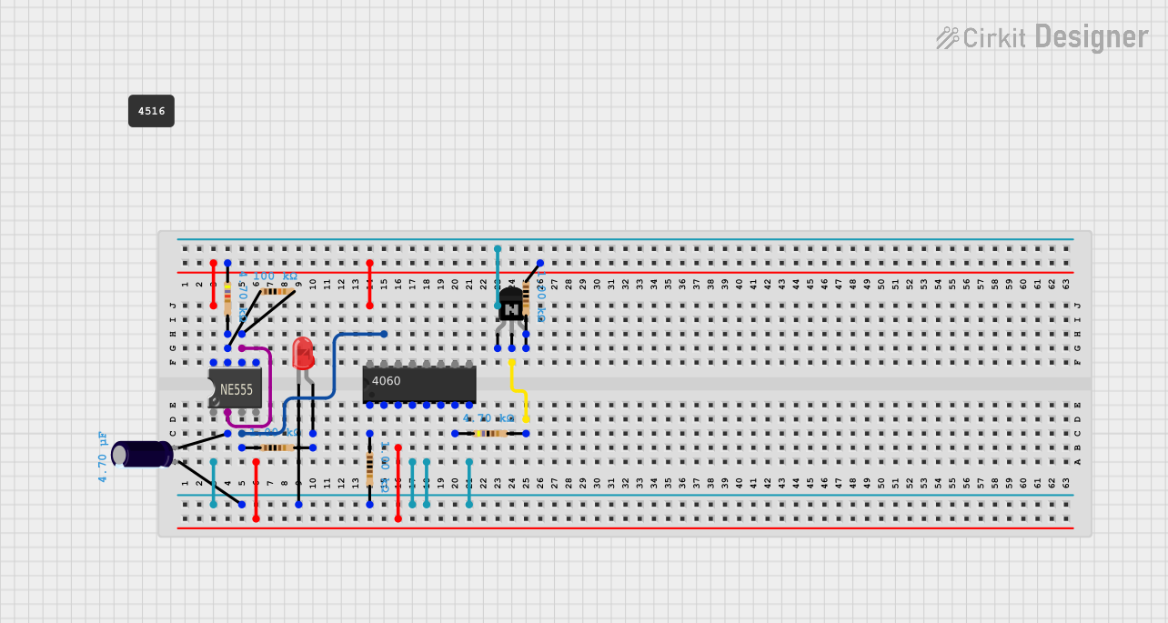

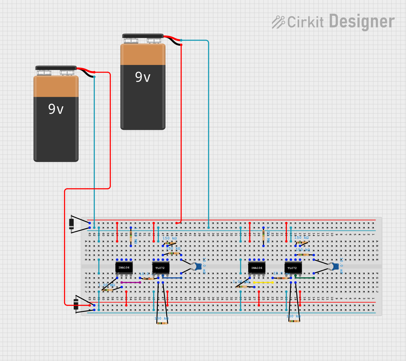
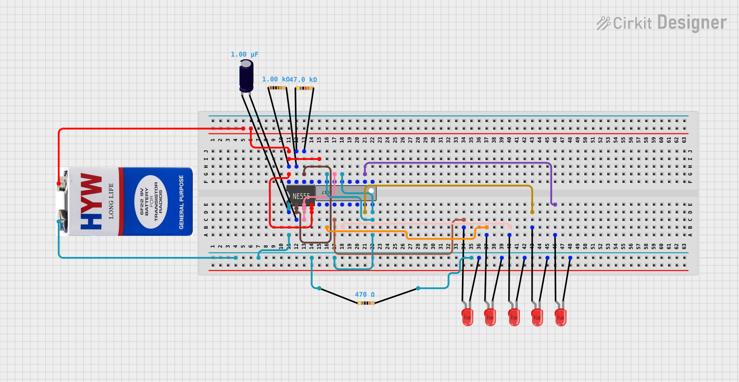
Explore Projects Built with 555
Technical Specifications
Key Technical Details
- Supply Voltage (Vcc): 4.5V to 15V
- Output Current (Iout): 200 mA (max)
- Power Dissipation: 600 mW
- Operating Temperature: -55°C to +125°C
- Timing Range: Microseconds to hours
- Frequency Range: Up to 500 kHz
Pin Configuration and Descriptions
| Pin Number | Name | Description |
|---|---|---|
| 1 | GND | Ground reference voltage, low level (0V) |
| 2 | TRIG | Triggers the timer (active low) |
| 3 | OUT | Output of the timer, drives load |
| 4 | RESET | Resets the timer (active low) |
| 5 | CTRL | Provides "control" access to the internal voltage divider (2/3 Vcc) |
| 6 | THRS | Threshold at which the timer's output changes state |
| 7 | DISCH | Discharge pin for the timing capacitor |
| 8 | Vcc | Positive supply voltage |
Usage Instructions
How to Use the Component in a Circuit
Astable Mode (Oscillator):
- Connect two resistors and a capacitor to set the frequency and duty cycle.
- The output will oscillate between high and low states without an external trigger.
Monostable Mode (One-shot):
- Use one resistor and one capacitor to set the time delay.
- A negative pulse on the trigger pin will cause the output to go high for the set time.
Bistable Mode (Flip-flop):
- The 555 can be used as a flip-flop if the threshold and trigger are connected to the output through a switch.
Important Considerations and Best Practices
- Ensure that the supply voltage (Vcc) is within the specified range.
- Decouple the power supply with a 0.1 µF capacitor close to the Vcc pin to reduce noise.
- Avoid connecting the output directly to a high current load; use a transistor if necessary.
- Use a diode in parallel with inductive loads to prevent voltage spikes.
Example Circuit: Blinking LED with 555 Timer
// Arduino code to blink an LED using a 555 timer in astable mode
const int ledPin = 13; // LED connected to digital pin 13

void setup() {
  pinMode(ledPin, OUTPUT); // sets the digital pin as output
}

void loop() {
  digitalWrite(ledPin, HIGH); // sets the LED on
  delay(1000);                // waits for a second
  digitalWrite(ledPin, LOW);  // sets the LED off
  delay(1000);                // waits for a second
}
Note: This code assumes the 555 timer is configured in astable mode to generate a square wave with a 50% duty cycle and a frequency that matches the Arduino's delay.
Troubleshooting and FAQs
Common Issues
- No Output: Check power supply, ensure the 555 timer is correctly powered.
- Output Always High or Low: Verify the connections of the trigger and threshold pins.
- Unstable Frequency: Ensure the timing capacitor and resistors are of the correct value and type.
Solutions and Tips
- If the output is not as expected, double-check the pin connections and component values.
- For frequency stability, use metal film resistors and a high-quality capacitor.
- Solderless breadboards can introduce unwanted capacitance and resistance; consider soldering a prototype.
FAQs
Q: Can I use the 555 timer at 3.3V? A: The standard 555 timer requires a minimum of 4.5V. For operation at 3.3V, use a CMOS version like the 7555.
Q: How can I adjust the frequency of the 555 timer? A: Change the values of the resistors and capacitor in the astable mode configuration.
Q: Is it possible to sync the 555 timer with an external clock? A: Yes, you can synchronize the 555 timer by applying an external clock signal to the trigger and threshold pins.
This documentation provides a comprehensive guide to the 555 timer IC, ensuring users can effectively incorporate it into their electronic projects.