How to Use 16 - Channel Analog Multiplexer: Examples, Pinouts, and Specs
Introduction
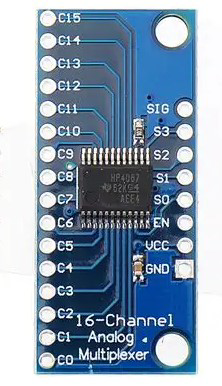
The 16-Channel Analog Multiplexer (Manufacturer: tyuyu, Part ID: yt7i8) is a versatile electronic component designed to route one of 16 analog input signals to a single output channel. This device is controlled using digital selection signals, making it ideal for applications requiring efficient signal routing and switching.
Explore Projects Built with 16 - Channel Analog Multiplexer


Explore Projects Built with 16 - Channel Analog Multiplexer
Common Applications and Use Cases
- Signal selection in data acquisition systems
- Expanding the number of analog inputs for microcontrollers
- Audio signal routing and mixing
- Sensor multiplexing in IoT devices
- Test and measurement equipment
Technical Specifications
The following table outlines the key technical details of the yt7i8 16-Channel Analog Multiplexer:
| Parameter | Value |
|---|---|
| Supply Voltage (Vcc) | 3V to 15V |
| Analog Input Voltage | 0V to Vcc |
| Control Logic Voltage | 0V to Vcc |
| On-Resistance (Ron) | ~70Ω (typical) |
| Propagation Delay | ~10ns |
| Maximum Current (Icc) | 1µA (standby), 1mA (active) |
| Operating Temperature | -40°C to +85°C |
| Package Type | DIP, SOIC |
Pin Configuration and Descriptions
The yt7i8 multiplexer has 16 input channels, 1 output channel, 4 control pins, and additional power and ground pins. Below is the pinout description:
| Pin Number | Pin Name | Description |
|---|---|---|
| 1-16 | IN0-IN15 | Analog input channels (0 to 15) |
| 17 | OUT | Analog output channel |
| 18 | Vcc | Positive power supply |
| 19 | GND | Ground |
| 20-23 | S0-S3 | Control pins for channel selection (binary encoded) |
| 24 | ENABLE | Active-low enable pin (must be LOW to operate) |
Usage Instructions
How to Use the Component in a Circuit
- Power Supply: Connect the Vcc pin to a stable power source (3V to 15V) and the GND pin to ground.
- Input Signals: Connect up to 16 analog signals to the IN0-IN15 pins.
- Output Signal: Connect the OUT pin to the desired destination (e.g., ADC input of a microcontroller).
- Control Signals: Use the S0-S3 pins to select the desired input channel. The selection is based on a 4-bit binary code:
- For example, to select IN3, set S3-S0 to
0011.
- For example, to select IN3, set S3-S0 to
- Enable Pin: Ensure the ENABLE pin is pulled LOW to activate the multiplexer. If HIGH, the device is disabled, and the output is disconnected.
Important Considerations and Best Practices
- Input Voltage Range: Ensure that the input signals do not exceed the supply voltage (Vcc).
- Decoupling Capacitor: Place a 0.1µF capacitor near the Vcc pin to reduce noise and stabilize the power supply.
- Unused Inputs: Tie unused input channels to ground or a fixed voltage to prevent floating inputs, which can cause noise.
- Control Signal Timing: Ensure that the control signals are stable before enabling the multiplexer to avoid glitches.
Example: Connecting to an Arduino UNO
Below is an example of how to use the yt7i8 multiplexer with an Arduino UNO to read multiple analog signals:
Circuit Connections
- Connect Vcc to the Arduino's 5V pin and GND to ground.
- Connect OUT to the Arduino's A0 pin.
- Connect S0-S3 to Arduino digital pins 2, 3, 4, and 5, respectively.
- Pull the ENABLE pin LOW by connecting it to ground.
Arduino Code
// Define control pins for the multiplexer
const int S0 = 2;  // Control pin S0
const int S1 = 3;  // Control pin S1
const int S2 = 4;  // Control pin S2
const int S3 = 5;  // Control pin S3
const int analogOut = A0;  // Multiplexer output connected to A0

void setup() {
  // Set control pins as outputs
  pinMode(S0, OUTPUT);
  pinMode(S1, OUTPUT);
  pinMode(S2, OUTPUT);
  pinMode(S3, OUTPUT);

  // Initialize serial communication for debugging
  Serial.begin(9600);
}

void loop() {
  for (int channel = 0; channel < 16; channel++) {
    // Set the control pins to select the desired channel
    digitalWrite(S0, channel & 0x01);  // Least significant bit
    digitalWrite(S1, (channel >> 1) & 0x01);
    digitalWrite(S2, (channel >> 2) & 0x01);
    digitalWrite(S3, (channel >> 3) & 0x01);

    // Read the analog value from the selected channel
    int value = analogRead(analogOut);

    // Print the channel number and value to the serial monitor
    Serial.print("Channel ");
    Serial.print(channel);
    Serial.print(": ");
    Serial.println(value);

    delay(500);  // Wait for 500ms before switching to the next channel
  }
}
Troubleshooting and FAQs
Common Issues and Solutions
No Output Signal:
- Ensure the ENABLE pin is LOW.
- Verify that the control signals (S0-S3) are correctly set for the desired channel.
- Check the power supply connections to Vcc and GND.
Incorrect or Noisy Output:
- Ensure the input signals are within the specified voltage range (0V to Vcc).
- Add a decoupling capacitor near the power supply pins to reduce noise.
- Avoid long wires for analog signals to minimize interference.
Floating Inputs:
- Tie unused input channels to ground or a fixed voltage to prevent noise.
FAQs
Q1: Can the multiplexer handle digital signals?
A1: Yes, the yt7i8 can route digital signals as long as they are within the specified voltage range.
Q2: What happens if the ENABLE pin is left floating?
A2: The ENABLE pin must be explicitly set to LOW for the multiplexer to function. If left floating, the behavior is undefined.
Q3: Can I cascade multiple multiplexers to handle more channels?
A3: Yes, you can cascade multiple multiplexers by connecting their outputs to additional multiplexers or microcontroller inputs. Ensure proper control signal management.
Q4: What is the maximum switching speed?
A4: The yt7i8 has a typical propagation delay of ~10ns, making it suitable for high-speed applications. However, the actual switching speed depends on the control signal timing.