How to Use MKR WAN 1310: Examples, Pinouts, and Specs
Introduction
The MKR WAN 1310 is a microcontroller board designed for Internet of Things (IoT) applications, offering long-range communication through LoRa technology. It is built around the SAMD21 Cortex-M0+ 32-bit ARM microcontroller and features a Murata CMWX1ZZABZ LoRa module for seamless connectivity. Additionally, the board includes a built-in battery charger, making it ideal for portable, battery-powered projects. Its compact size and versatile features make it a popular choice for IoT developers.
Explore Projects Built with MKR WAN 1310
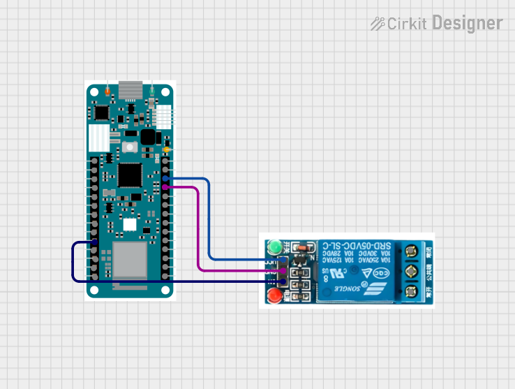
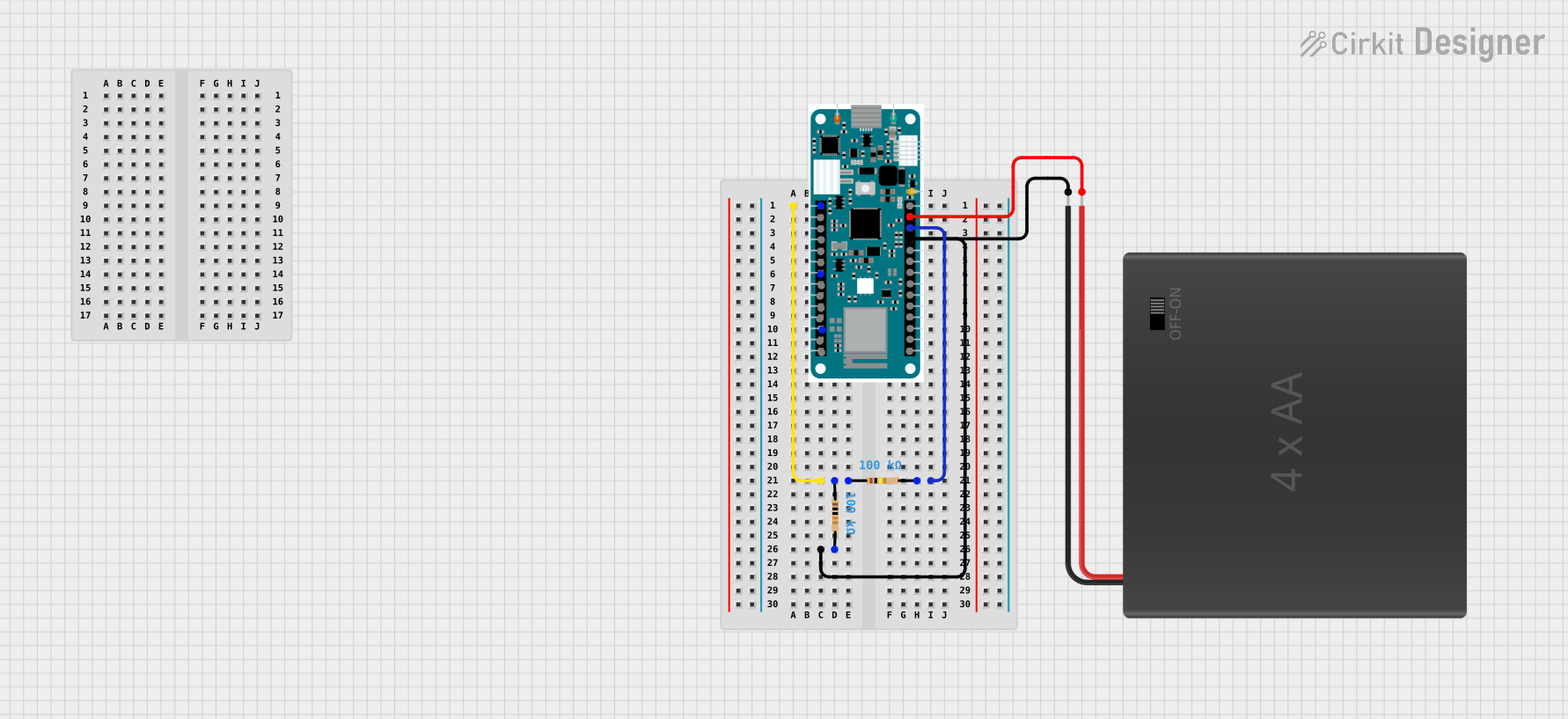

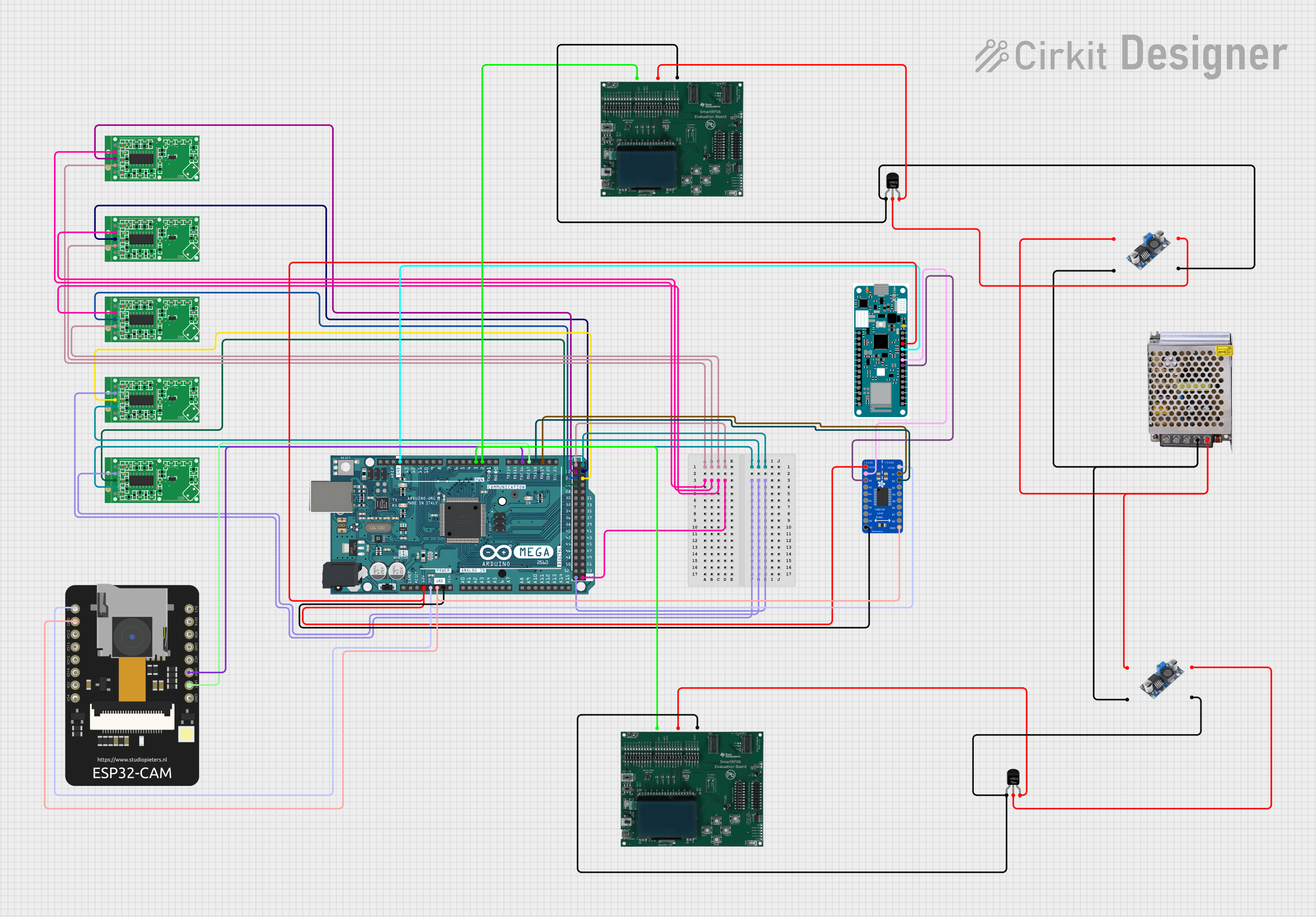
Explore Projects Built with MKR WAN 1310
Common Applications and Use Cases
- Smart agriculture and environmental monitoring
- Industrial IoT (IIoT) applications
- Remote sensing and data logging
- Smart cities and infrastructure
- Battery-powered IoT devices with long-range communication
Technical Specifications
Key Technical Details
- Microcontroller: SAMD21 Cortex-M0+ 32-bit ARM
- LoRa Module: Murata CMWX1ZZABZ
- Operating Voltage: 3.3V
- Input Voltage (Vin): 5V via USB or 5-12V via Vin pin
- Digital I/O Pins: 8 (of which 4 can be used as PWM outputs)
- Analog Input Pins: 7 (12-bit ADC)
- Analog Output Pins: 1 (10-bit DAC)
- Flash Memory: 256 KB
- SRAM: 32 KB
- Clock Speed: 48 MHz
- Connectivity: LoRa, UART, I2C, SPI
- Battery Support: Li-Po single-cell, 3.7V, 1024mAh (minimum recommended)
- Dimensions: 67.64mm x 25mm
- Weight: 32g
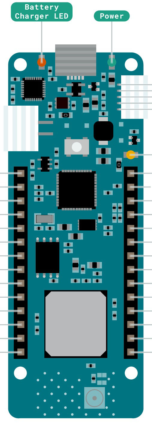
Pin Configuration and Descriptions
| Pin | Name | Description |
|---|---|---|
| 1 | Vin | Input voltage pin (5-12V) for powering the board externally. |
| 2 | 5V | Regulated 5V output (USB-powered). |
| 3 | 3.3V | Regulated 3.3V output. |
| 4 | GND | Ground pin. |
| 5 | A0-A6 | Analog input pins (12-bit ADC). |
| 6 | D0-D7 | Digital I/O pins (4 PWM-capable). |
| 7 | RX/TX | UART communication pins. |
| 8 | I2C (SDA/SCL) | I2C communication pins. |
| 9 | SPI (MISO/MOSI/SCK) | SPI communication pins for high-speed data transfer. |
| 10 | RST | Reset pin to restart the board. |
| 11 | Li-Po Battery | Connector for a 3.7V Li-Po battery. |
Usage Instructions
How to Use the MKR WAN 1310 in a Circuit
Powering the Board:
- Connect the board to a computer or USB power source using a micro-USB cable.
- Alternatively, supply 5-12V to the Vin pin or connect a 3.7V Li-Po battery to the battery connector.
Programming the Board:
- Install the Arduino IDE and add the MKR WAN 1310 board via the Arduino SAMD Boards package.
- Select the correct board and port in the Arduino IDE before uploading your code.
Connecting to LoRa:
- Use the LoRa library in the Arduino IDE to configure and send/receive data.
- Ensure the LoRa gateway is within range and configured to the same frequency as the MKR WAN 1310.
Connecting Sensors and Actuators:
- Use the analog (A0-A6) and digital (D0-D7) pins to interface with sensors and actuators.
- For I2C devices, connect to the SDA and SCL pins, and for SPI devices, use the MISO, MOSI, and SCK pins.
Important Considerations and Best Practices
- Battery Usage: Always use a 3.7V Li-Po battery with a minimum capacity of 1024mAh for optimal performance.
- Voltage Levels: The board operates at 3.3V logic levels. Avoid connecting 5V signals directly to the pins.
- Antenna Connection: Ensure the LoRa antenna is securely connected to the board for proper communication.
- Frequency Configuration: Verify that the LoRa frequency matches the regional regulations (e.g., 868 MHz for Europe, 915 MHz for the US).
Example Code for LoRa Communication with Arduino UNO
#include <LoRa.h> // Include the LoRa library

void setup() {
  Serial.begin(9600); // Initialize serial communication at 9600 baud
  while (!Serial);

  Serial.println("Initializing LoRa...");

  // Initialize LoRa with frequency (e.g., 915E6 for 915 MHz)
  if (!LoRa.begin(915E6)) {
    Serial.println("LoRa initialization failed!");
    while (1);
  }

  Serial.println("LoRa initialized successfully.");
}

void loop() {
  Serial.println("Sending packet...");

  // Begin a LoRa packet
  LoRa.beginPacket();
  LoRa.print("Hello, LoRa!"); // Add data to the packet
  LoRa.endPacket(); // Send the packet

  delay(5000); // Wait 5 seconds before sending the next packet
}
Troubleshooting and FAQs
Common Issues and Solutions
LoRa Initialization Fails:
- Ensure the LoRa antenna is properly connected.
- Verify that the frequency set in the code matches the regional frequency.
- Check the power supply to ensure the board is receiving sufficient voltage.
Board Not Recognized by Arduino IDE:
- Confirm that the correct board and port are selected in the Arduino IDE.
- Reinstall the Arduino SAMD Boards package if necessary.
- Try using a different USB cable or port.
Battery Not Charging:
- Ensure the Li-Po battery is connected correctly to the battery connector.
- Verify that the board is powered via USB or Vin while charging.
No LoRa Communication:
- Check the range and ensure there are no obstructions between the MKR WAN 1310 and the LoRa gateway.
- Verify that both devices are configured to the same frequency and spreading factor.
FAQs
Can the MKR WAN 1310 operate without a battery?
Yes, the board can be powered via USB or Vin without a battery.What is the maximum range of LoRa communication?
The range depends on environmental factors but can reach up to 10 km in open areas.Is the MKR WAN 1310 compatible with other LoRa devices?
Yes, as long as the devices operate on the same frequency and protocol.Can I use the MKR WAN 1310 with other Arduino shields?
Yes, the board is compatible with MKR form-factor shields.