How to Use BNO055 9 DOF Absolute Orientation IMU Module: Examples, Pinouts, and Specs
Introduction
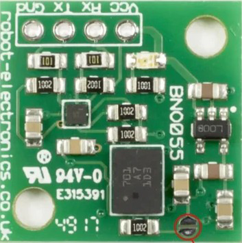
The BNO055 is a highly integrated sensor module manufactured by Pololu (Part ID: BNO055). It combines a 3-axis accelerometer, 3-axis gyroscope, and 3-axis magnetometer to provide absolute orientation in 3D space. Unlike traditional IMUs, the BNO055 features an onboard sensor fusion algorithm, which processes raw sensor data to output orientation in Euler angles (roll, pitch, yaw) or quaternion format. This eliminates the need for complex external computations, making it a plug-and-play solution for motion tracking.
Explore Projects Built with BNO055 9 DOF Absolute Orientation IMU Module


Explore Projects Built with BNO055 9 DOF Absolute Orientation IMU Module
Common Applications and Use Cases
- Robotics and autonomous vehicles
- Drones and UAVs for stabilization and navigation
- Virtual reality (VR) and augmented reality (AR) systems
- Wearable devices for motion tracking
- Industrial automation and control systems
Technical Specifications
The following table outlines the key technical details of the BNO055 module:
| Parameter | Value |
|---|---|
| Operating Voltage | 2.4V to 3.6V (3.3V typical) |
| Communication Interfaces | I²C (default), UART |
| I²C Address (Default) | 0x28 (can be changed to 0x29) |
| Gyroscope Range | ±125°/s, ±250°/s, ±500°/s, ±1000°/s, ±2000°/s |
| Accelerometer Range | ±2g, ±4g, ±8g, ±16g |
| Magnetometer Range | ±1300 µT |
| Orientation Output | Euler angles, Quaternion, Linear Acceleration |
| Power Consumption | 12 mA (typical) |
| Operating Temperature Range | -40°C to +85°C |
| Dimensions | 3.8 mm x 5.2 mm x 1.1 mm |
Pin Configuration and Descriptions
The BNO055 module has the following pinout:
| Pin | Name | Description |
|---|---|---|
| 1 | VIN | Power supply input (2.4V to 3.6V, typically 3.3V). |
| 2 | GND | Ground connection. |
| 3 | SDA | I²C data line. |
| 4 | SCL | I²C clock line. |
| 5 | PS0 | Protocol selection pin 0 (used to select I²C or UART mode). |
| 6 | PS1 | Protocol selection pin 1 (used to select I²C or UART mode). |
| 7 | RST | Reset pin (active low). |
| 8 | INT | Interrupt pin (can be configured for various interrupt sources). |
| 9 | TX | UART transmit line (used in UART mode). |
| 10 | RX | UART receive line (used in UART mode). |
Usage Instructions
How to Use the BNO055 in a Circuit
- Power the Module: Connect the VIN pin to a 3.3V power source and GND to ground.
- Select Communication Protocol:
- For I²C: Connect PS0 to GND and PS1 to GND.
- For UART: Connect PS0 to VCC and PS1 to GND.
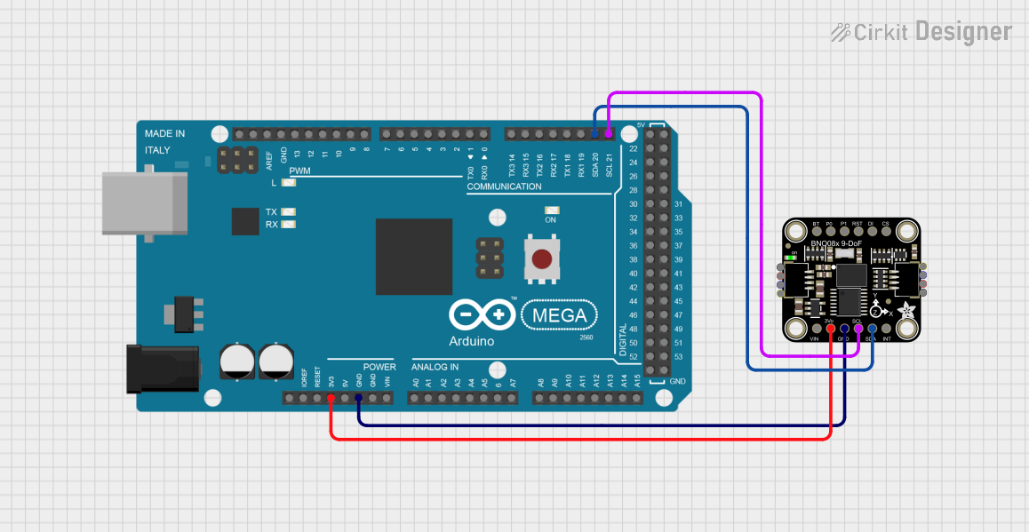
- Connect Communication Lines:
- For I²C: Connect SDA and SCL to the corresponding pins on your microcontroller.
- For UART: Connect TX and RX to the UART pins on your microcontroller.
- Pull-Up Resistors: If using I²C, ensure pull-up resistors (typically 4.7 kΩ) are present on the SDA and SCL lines.
- Initialize the Module: Use the appropriate library or commands to initialize the BNO055 and configure its settings.
Important Considerations and Best Practices
- Power Supply: Ensure a stable 3.3V power supply to avoid erratic behavior.
- Orientation Calibration: Perform a calibration routine for the accelerometer, gyroscope, and magnetometer to ensure accurate orientation data.
- Mounting: Secure the module firmly to minimize vibrations, which can affect sensor readings.
- Magnetic Interference: Avoid placing the module near strong magnetic fields, as they can distort magnetometer readings.
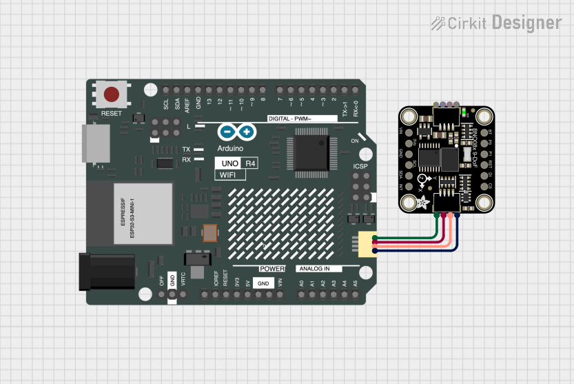
Example: Using the BNO055 with Arduino UNO
Below is an example of how to interface the BNO055 with an Arduino UNO using I²C:
#include <Wire.h>
#include <Adafruit_Sensor.h>
#include <Adafruit_BNO055.h>

// Create an instance of the BNO055 sensor
Adafruit_BNO055 bno = Adafruit_BNO055(55, 0x28);

void setup() {
  Serial.begin(9600); // Initialize serial communication
  Serial.println("BNO055 Test");

  // Initialize the BNO055 sensor
  if (!bno.begin()) {
    Serial.println("Failed to initialize BNO055! Check connections.");
    while (1);
  }

  // Set the sensor to NDOF mode (sensor fusion for absolute orientation)
  bno.setMode(Adafruit_BNO055::OPERATION_MODE_NDOF);

  Serial.println("BNO055 initialized successfully!");
  delay(1000);
}

void loop() {
  // Get Euler angles (roll, pitch, yaw)
  sensors_event_t event;
  bno.getEvent(&event);

  Serial.print("Roll: ");
  Serial.print(event.orientation.x);
  Serial.print(" Pitch: ");
  Serial.print(event.orientation.y);
  Serial.print(" Yaw: ");
  Serial.println(event.orientation.z);

  delay(500); // Delay for readability
}
Notes:
- Install the Adafruit BNO055 library via the Arduino Library Manager before running the code.
- Ensure the I²C address (0x28) matches the module's configuration.
Troubleshooting and FAQs
Common Issues and Solutions
Sensor Not Detected:
- Ensure the correct I²C address (0x28 or 0x29) is being used.
- Check the wiring for loose or incorrect connections.
- Verify that pull-up resistors are present on the SDA and SCL lines.
Inaccurate Orientation Data:
- Perform a full calibration of the accelerometer, gyroscope, and magnetometer.
- Avoid placing the module near sources of magnetic interference.
Module Not Responding:
- Check the power supply voltage (should be 3.3V).
- Ensure the PS0 and PS1 pins are configured correctly for the desired communication protocol.
Random Resets:
- Verify that the power supply can provide sufficient current (at least 12 mA).
- Check for noise or instability in the power supply.
FAQs
Q: Can the BNO055 output raw sensor data?
A: Yes, the BNO055 can output raw accelerometer, gyroscope, and magnetometer data in addition to fused orientation data.
Q: How do I reset the module?
A: Pull the RST pin low for at least 1 ms, then release it to reset the module.
Q: Can I use the BNO055 with a 5V microcontroller?
A: Yes, but you must use a level shifter for the I²C or UART lines, as the BNO055 operates at 3.3V logic levels.
Q: How do I change the I²C address?
A: Connect the ADR pin to VCC to change the I²C address from 0x28 to 0x29.
By following this documentation, you can effectively integrate the BNO055 into your projects for precise motion tracking and orientation sensing.