How to Use BUCK: Examples, Pinouts, and Specs
Introduction
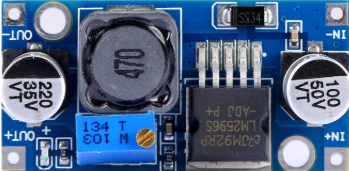
The BUCK DC/DC converter, manufactured by HUAREW, is a highly efficient DC-DC step-down voltage regulator. It is designed to convert a higher input voltage to a lower output voltage while maintaining high efficiency and stepping up the current. This component is widely used in power management systems, battery-powered devices, and embedded systems where efficient voltage regulation is critical.
Explore Projects Built with BUCK


Explore Projects Built with BUCK
Common Applications and Use Cases
- Power supply for microcontrollers and embedded systems
- Battery-powered devices (e.g., portable electronics, IoT devices)
- Voltage regulation in renewable energy systems
- LED drivers and lighting systems
- Automotive electronics
Technical Specifications
The following table outlines the key technical specifications of the HUAREW BUCK DC/DC converter:
| Parameter | Value |
|---|---|
| Input Voltage Range | 4.5V to 40V |
| Output Voltage Range | 1.2V to 36V |
| Output Current | Up to 3A |
| Efficiency | Up to 95% |
| Switching Frequency | 150 kHz |
| Operating Temperature | -40°C to +85°C |
| Package Type | TO-220 or SMD (varies by model) |
Pin Configuration and Descriptions
The BUCK DC/DC converter typically has the following pin configuration:
| Pin Number | Pin Name | Description |
|---|---|---|
| 1 | VIN | Input voltage pin. Connect to the higher input voltage source. |
| 2 | GND | Ground pin. Connect to the system ground. |
| 3 | VOUT | Output voltage pin. Provides the regulated lower voltage. |
| 4 | EN (optional) | Enable pin. Used to turn the converter on or off. |
| 5 | FB (optional) | Feedback pin. Used for voltage regulation and adjustment. |
Usage Instructions
How to Use the BUCK DC/DC Converter in a Circuit
Connect the Input Voltage (VIN):
Attach the input voltage source (e.g., a battery or power supply) to the VIN pin. Ensure the input voltage is within the specified range (4.5V to 40V).Connect the Ground (GND):
Connect the GND pin to the system ground to complete the circuit.Connect the Output Voltage (VOUT):
Attach the load or device requiring the regulated voltage to the VOUT pin. Ensure the load does not exceed the maximum output current (3A).Optional Pins:
- If the EN pin is available, connect it to a logic HIGH signal to enable the converter or to a logic LOW signal to disable it.
- Use the FB pin to adjust the output voltage by connecting it to a resistor divider network.
Add External Components:
- Place an input capacitor (e.g., 10µF) between VIN and GND to stabilize the input voltage.
- Place an output capacitor (e.g., 22µF) between VOUT and GND to reduce output voltage ripple.
- Use an inductor with appropriate current ratings for the desired output voltage and current.
Important Considerations and Best Practices
- Heat Dissipation: Ensure proper heat dissipation by using a heatsink or adequate ventilation, especially for high-current applications.
- Inductor Selection: Choose an inductor with a current rating higher than the maximum output current to avoid saturation.
- Output Voltage Adjustment: If the FB pin is used, calculate the resistor divider values carefully to achieve the desired output voltage.
- Input Voltage Range: Always ensure the input voltage is within the specified range to prevent damage to the converter.
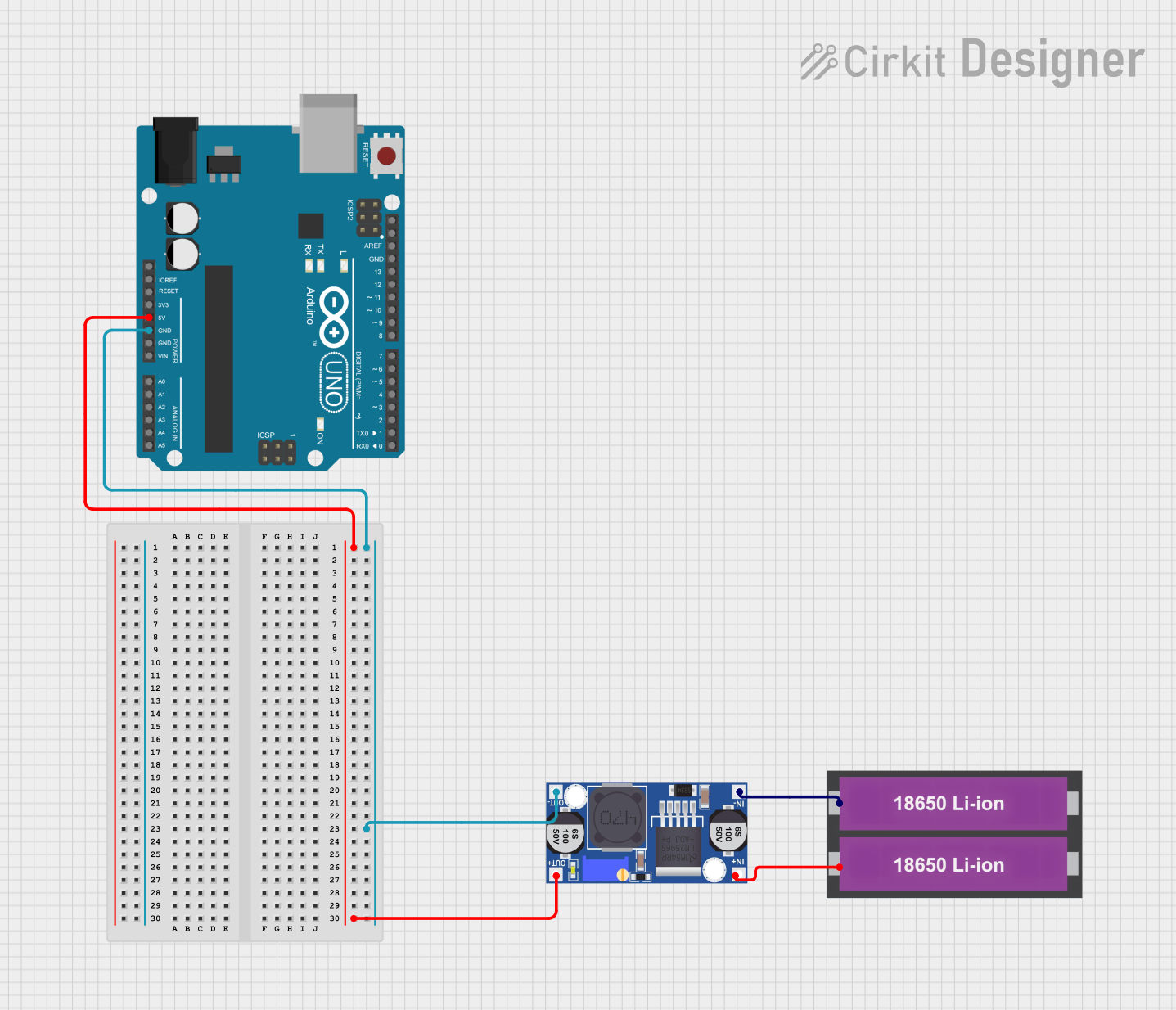
Example: Connecting to an Arduino UNO
The BUCK DC/DC converter can be used to power an Arduino UNO by stepping down a higher voltage (e.g., 12V) to 5V. Below is an example circuit and Arduino code:
Circuit Setup
- Connect a 12V power supply to the VIN pin of the BUCK converter.
- Connect the GND pin of the BUCK converter to the Arduino GND.
- Set the output voltage of the BUCK converter to 5V using the FB pin (if adjustable).
- Connect the VOUT pin of the BUCK converter to the 5V pin of the Arduino UNO.
Arduino Code Example
// Example code to blink an LED using an Arduino UNO powered by a BUCK DC/DC converter

const int ledPin = 13; // Pin connected to the onboard LED

void setup() {
  pinMode(ledPin, OUTPUT); // Set the LED pin as an output
}

void loop() {
  digitalWrite(ledPin, HIGH); // Turn the LED on
  delay(1000);               // Wait for 1 second
  digitalWrite(ledPin, LOW);  // Turn the LED off
  delay(1000);               // Wait for 1 second
}
Troubleshooting and FAQs
Common Issues and Solutions
No Output Voltage:
- Cause: Input voltage is not connected or is outside the specified range.
Solution: Verify the input voltage and ensure it is within 4.5V to 40V. - Cause: EN pin is not enabled (if applicable).
Solution: Connect the EN pin to a logic HIGH signal to enable the converter.
- Cause: Input voltage is not connected or is outside the specified range.
Excessive Heat:
- Cause: Overloading the converter with a current higher than 3A.
Solution: Reduce the load current or use a heatsink for better heat dissipation. - Cause: Insufficient ventilation.
Solution: Ensure proper airflow around the converter.
- Cause: Overloading the converter with a current higher than 3A.
High Output Voltage Ripple:
- Cause: Missing or insufficient output capacitor.
Solution: Add a capacitor (e.g., 22µF) between VOUT and GND.
- Cause: Missing or insufficient output capacitor.
Incorrect Output Voltage:
- Cause: Misconfigured feedback resistor network (if adjustable).
Solution: Recalculate and adjust the resistor values for the desired output voltage.
- Cause: Misconfigured feedback resistor network (if adjustable).
FAQs
Q1: Can the BUCK DC/DC converter be used with a 24V input to power a 5V device?
A1: Yes, the converter can step down a 24V input to 5V, provided the output current does not exceed 3A.
Q2: What happens if the input voltage exceeds 40V?
A2: Exceeding the maximum input voltage may damage the converter. Always ensure the input voltage is within the specified range.
Q3: Can I use the BUCK DC/DC converter to power multiple devices?
A3: Yes, as long as the total current draw of all devices does not exceed the maximum output current (3A).
Q4: Is the BUCK DC/DC converter suitable for battery charging?
A4: While it can regulate voltage, additional circuitry may be required for proper battery charging to prevent overcharging or damage.