How to Use ESP 32U: Examples, Pinouts, and Specs
Introduction
The ESP 32U is a low-cost, low-power system on a chip (SoC) with integrated Wi-Fi and Bluetooth capabilities. It is designed for a wide range of applications, particularly in the Internet of Things (IoT) domain. The ESP 32U combines a powerful dual-core processor with advanced wireless communication features, making it ideal for projects requiring connectivity, control, and data processing.
Explore Projects Built with ESP 32U


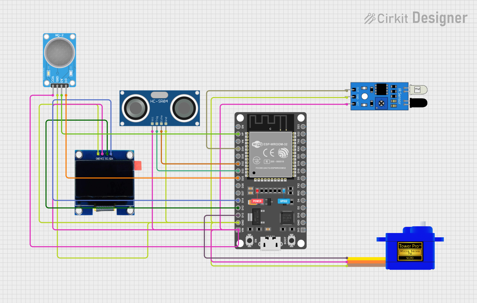
Explore Projects Built with ESP 32U
Common Applications and Use Cases
- Smart home devices (e.g., smart lights, thermostats, and security systems)
- Industrial IoT systems for monitoring and automation
- Wearable devices with wireless communication
- Wireless sensor networks
- Robotics and remote-controlled systems
- Prototyping and development of connected devices
Technical Specifications
The ESP 32U is a highly versatile module with the following key technical specifications:
| Parameter | Specification |
|---|---|
| Processor | Dual-core Xtensa® 32-bit LX6 microprocessor |
| Clock Speed | Up to 240 MHz |
| Flash Memory | 4 MB (external SPI flash) |
| RAM | 520 KB SRAM |
| Wi-Fi | 802.11 b/g/n (2.4 GHz) |
| Bluetooth | Bluetooth 4.2 and BLE |
| Operating Voltage | 3.0V to 3.6V |
| GPIO Pins | 34 (multipurpose, including ADC, DAC, PWM, etc.) |
| ADC Channels | 18 (12-bit resolution) |
| DAC Channels | 2 (8-bit resolution) |
| Communication Interfaces | UART, SPI, I2C, I2S, CAN, Ethernet MAC, SDIO |
| Power Consumption | Ultra-low power (varies by mode: active, sleep, etc.) |
| Operating Temperature | -40°C to +85°C |
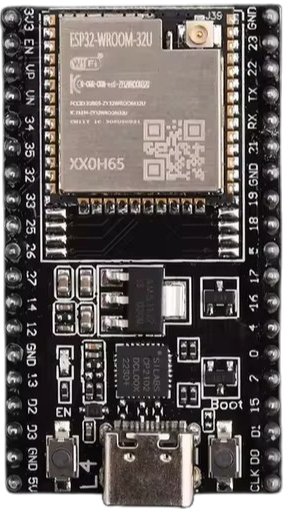
Pin Configuration and Descriptions
The ESP 32U module has a variety of pins for different functionalities. Below is a summary of the pin configuration:
| Pin | Name | Description |
|---|---|---|
| 1 | GND | Ground connection |
| 2 | 3V3 | Power supply (3.3V input) |
| 3 | EN | Enable pin (active high, used to reset the chip) |
| 4 | GPIO0 | General-purpose I/O, boot mode selection |
| 5 | GPIO1 (TX0) | UART0 transmit pin |
| 6 | GPIO3 (RX0) | UART0 receive pin |
| 7 | GPIO16 | General-purpose I/O |
| 8 | GPIO17 | General-purpose I/O |
| 9 | ADC1_CH0 | Analog-to-digital converter channel 0 |
| 10 | DAC1 | Digital-to-analog converter channel 1 |
| ... | ... | Additional GPIO pins with various functionalities |
For a complete pinout diagram, refer to the ESP 32U datasheet.
Usage Instructions
How to Use the ESP 32U in a Circuit
- Power Supply: Connect the 3V3 pin to a stable 3.3V power source and GND to ground.
- Programming: Use a USB-to-serial adapter to connect the ESP 32U to your computer. Connect:
- TX on the adapter to RX0 (GPIO3) on the ESP 32U.
- RX on the adapter to TX0 (GPIO1) on the ESP 32U.
- GND on the adapter to GND on the ESP 32U.
- Boot Mode: To upload code, hold the GPIO0 pin low (connect to GND) while resetting the chip.
- GPIO Usage: Use the GPIO pins for interfacing with sensors, actuators, and other peripherals. Ensure the voltage levels are compatible with the ESP 32U (3.3V logic).
Important Considerations and Best Practices
- Voltage Levels: Avoid applying voltages higher than 3.3V to any pin to prevent damage.
- Power Supply: Use a low-noise, stable power source to ensure reliable operation.
- Antenna Placement: Ensure the onboard antenna has sufficient clearance from metal objects to avoid interference.
- Heat Management: If operating at high loads, consider adding a heatsink or ensuring proper ventilation.
Example Code for Arduino UNO Integration
The ESP 32U can be programmed using the Arduino IDE. Below is an example of connecting the ESP 32U to a Wi-Fi network:
#include <WiFi.h> // Include the Wi-Fi library for ESP32

const char* ssid = "Your_SSID";       // Replace with your Wi-Fi network name
const char* password = "Your_Password"; // Replace with your Wi-Fi password

void setup() {
  Serial.begin(115200); // Initialize serial communication at 115200 baud
  delay(1000);          // Wait for a moment before starting

  Serial.println("Connecting to Wi-Fi...");
  WiFi.begin(ssid, password); // Start connecting to the Wi-Fi network

  while (WiFi.status() != WL_CONNECTED) {
    delay(500); // Wait for connection
    Serial.print(".");
  }

  Serial.println("\nWi-Fi connected!");
  Serial.print("IP Address: ");
  Serial.println(WiFi.localIP()); // Print the assigned IP address
}

void loop() {
  // Add your main code here
}
Troubleshooting and FAQs
Common Issues and Solutions
ESP 32U Not Connecting to Wi-Fi
- Solution: Double-check the SSID and password. Ensure the Wi-Fi network is 2.4 GHz, as the ESP 32U does not support 5 GHz networks.
Code Upload Fails
- Solution: Ensure the GPIO0 pin is held low during the reset process. Verify the USB-to-serial adapter is properly connected.
Unstable Operation
- Solution: Check the power supply for noise or instability. Use capacitors to filter the power supply if necessary.
GPIO Pin Not Responding
- Solution: Verify the pin mode is correctly set in the code (e.g.,
pinMode(pin, OUTPUT);). Ensure the connected device is functioning properly.
- Solution: Verify the pin mode is correctly set in the code (e.g.,
FAQs
Can the ESP 32U operate on battery power? Yes, the ESP 32U is designed for low-power operation and can run on batteries. Use a 3.3V regulator if necessary.
Is the ESP 32U compatible with Arduino libraries? Yes, the ESP 32U can be programmed using the Arduino IDE and supports most Arduino libraries.
How do I reset the ESP 32U? Pull the EN pin low momentarily to reset the chip.
For additional support, refer to the official ESP 32U datasheet and community forums.