The SparkFun nRF52832 Breakout is a versatile and powerful development board designed for Bluetooth Low Energy (BLE) applications. Based on the Nordic Semiconductor nRF52832 System-on-Chip (SoC), this breakout board is ideal for engineers and hobbyists looking to integrate BLE functionality into their projects. With its small form factor and low power consumption, it is particularly well-suited for wearable devices, IoT sensors, and smart home applications.
Explore Projects Built with SparkFun nRF52832 Breakout
Use Cirkit Designer to design, explore, and prototype these projects online. Some projects support real-time simulation. Click "Open Project" to start designing instantly!
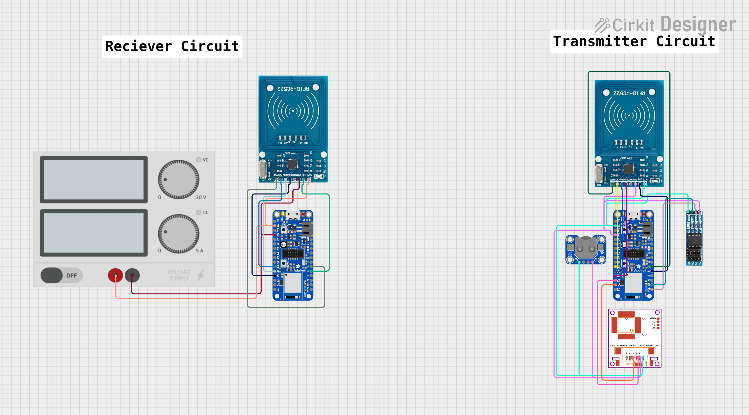
This circuit features two Adafruit Feather nRF52840 microcontrollers, each interfaced with an RFID-RC522 module for RFID communication and an AT24C256 external EEPROM for additional memory storage. One of the microcontrollers is also connected to an R307 Fingerprint Sensor for biometric input, and both microcontrollers are powered by a shared power supply and a coin cell breakout for backup or RTC power. The circuit is likely designed for secure access control or identification purposes, utilizing both RFID and fingerprint authentication, with data storage capabilities.
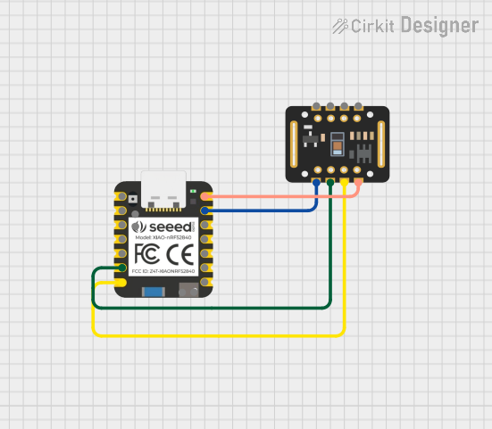
This circuit integrates a Seeed Studio nRF52840 microcontroller with a MAX30102 sensor module. The microcontroller powers the sensor and communicates with it via I2C protocol, enabling functionalities such as heart rate and SpO2 monitoring.
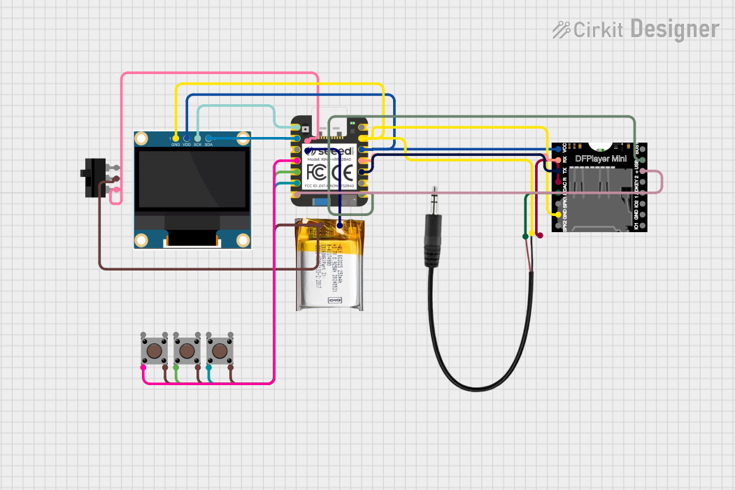
This circuit is an MP3 player system controlled by a Seeed Studio nRF52840 microcontroller. It includes a DFPlayer MINI for audio playback, a 0.96" OLED display for visual feedback, and multiple pushbuttons for user interaction. The system is powered by a 3.7V LiPo battery and outputs audio through a 3.5mm audio jack.
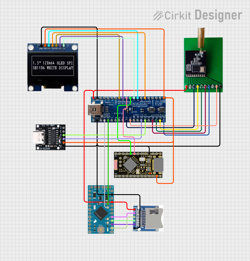
This circuit integrates multiple microcontrollers (Maple Mini STM32F1, nRF52840 ProMicro, and Arduino Pro Mini) to interface with various peripherals including an SSD1306 OLED display, an SD card module, and a Si4463 RF module. The circuit is designed for data acquisition, storage, and wireless communication, with power supplied through a USB Serial TTL module.
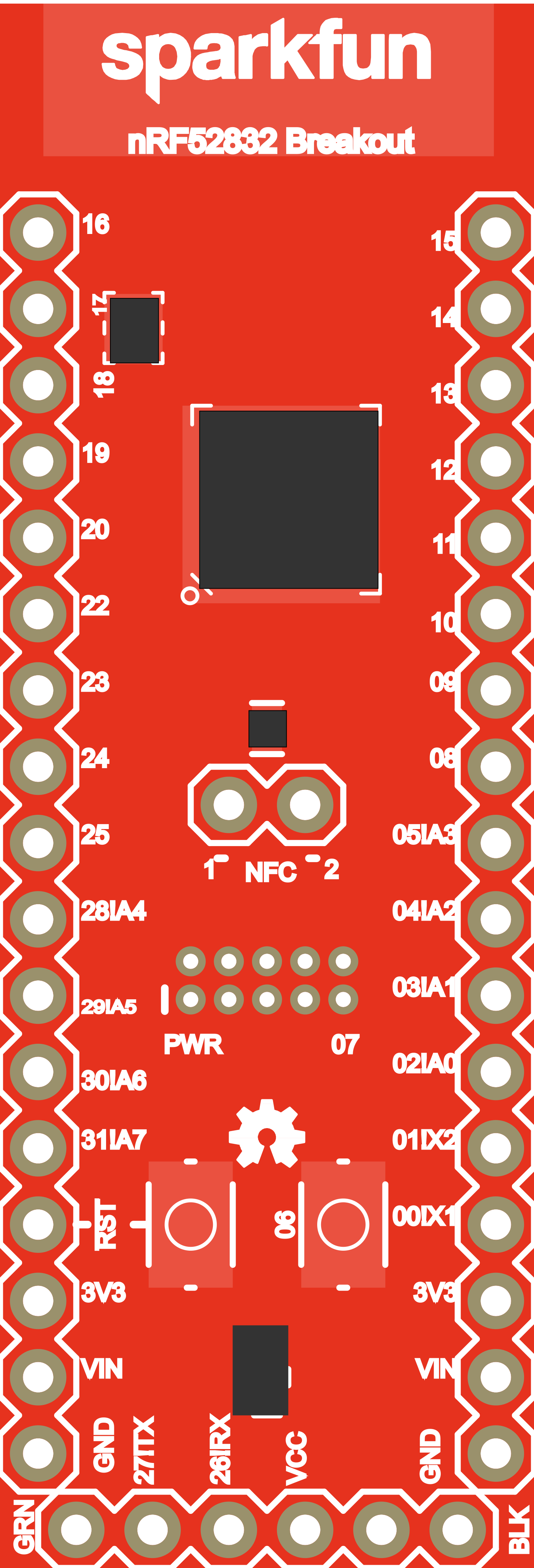
Power Supply: Connect a power source of 1.7V to 3.6V to the VDD pin and connect the GND pin to the ground of your power supply.
Programming: Use the UART pins to interface with a serial programmer for uploading firmware.
GPIO: Utilize the GPIO pins for interfacing with sensors, actuators, or other peripherals.
ADC: Connect analog sensors to ADC pins for reading analog values.
PWM: Use PWM pins to control motors or LEDs with varying intensity.
Communication: Implement SPI or I2C communication by connecting the respective pins to your peripherals.
Best Practices
Ensure that the power supply is within the specified voltage range to prevent damage.
Use pull-up or pull-down resistors on GPIO pins if required by your circuit design.
When using ADC inputs, ensure that the input voltage does not exceed the reference voltage.
For BLE functionality, ensure that the antenna is properly connected and positioned for optimal signal strength.
Example Code for Arduino UNO
// Include the required BLE library
#include <BLEPeripheral.h>

// Define the BLE Peripheral
BLEPeripheral blePeripheral;

// Setup BLE service and characteristics
BLEService ledService("19B10000-E8F2-537E-4F6C-D104768A1214");
BLECharCharacteristic switchCharacteristic("19B10001-E8F2-537E-4F6C-D104768A1214", BLEWrite);

void setup() {
  // Begin BLE Peripheral
  blePeripheral.setLocalName("LED Control");
  blePeripheral.setAdvertisedServiceUuid(ledService.uuid());
  blePeripheral.addAttribute(ledService);
  blePeripheral.addAttribute(switchCharacteristic);
  blePeripheral.begin();

  pinMode(LED_BUILTIN, OUTPUT);
}

void loop() {
  // Poll for BLE events
  blePeripheral.poll();

  // Check if characteristic value was written
  if (switchCharacteristic.written()) {
    if (switchCharacteristic.value()) {
      digitalWrite(LED_BUILTIN, HIGH); // Turn on LED if value is 1
    } else {
      digitalWrite(LED_BUILTIN, LOW);  // Turn off LED if value is 0
    }
  }
}
Troubleshooting and FAQs
Common Issues
Device not powering on: Ensure that the power supply is connected correctly and within the specified voltage range.
BLE not functioning: Verify that the antenna is properly connected and that there are no obstructions causing signal interference.
Inconsistent communication: Check the wiring and connections for SPI/I2C/UART interfaces, and ensure that the correct communication protocols are being used in your code.
Solutions and Tips
Power issues: Use a multimeter to check the voltage at the VDD pin.
Signal strength: Position the antenna away from metal objects and electronic interference.
Firmware updates: Regularly update the firmware to the latest version to ensure compatibility and performance improvements.
FAQs
Q: Can the nRF52832 Breakout be used with a 5V system?
A: No, the operating voltage is 1.7V to 3.6V. Level shifters should be used for interfacing with 5V systems.
Q: How do I update the firmware on the nRF52832 Breakout?
A: Firmware can be updated using a serial programmer and the UART pins. Nordic's nRF5 SDK and tools can be used for firmware development and updates.
Q: What is the range of the BLE on the nRF52832 Breakout?
A: The range can vary depending on environmental factors but typically is up to 100 meters line-of-sight with proper antenna configuration.

 Open Project in Cirkit Designer