How to Use esp32-WROOM: Examples, Pinouts, and Specs
Introduction
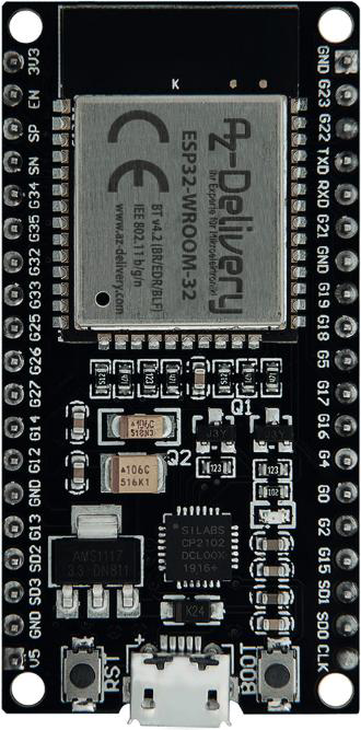
The ESP32-WROOM, manufactured by AZ-Delivery, is a versatile and powerful microcontroller module designed for Internet of Things (IoT) applications. It integrates Wi-Fi and Bluetooth capabilities, enabling seamless wireless communication. With its dual-core processor, extensive GPIO pins, and support for multiple communication protocols, the ESP32-WROOM is ideal for building connected devices, smart home systems, industrial automation, and more.
Explore Projects Built with esp32-WROOM


Explore Projects Built with esp32-WROOM
Common Applications and Use Cases
- IoT devices and smart home automation
- Wireless sensor networks
- Wearable technology
- Industrial control systems
- Robotics and automation
- Prototyping and educational projects
Technical Specifications
The ESP32-WROOM module is packed with features that make it suitable for a wide range of applications. Below are its key technical specifications:
Key Technical Details
| Parameter | Specification |
|---|---|
| Microcontroller | Tensilica Xtensa LX6 Dual-Core |
| Clock Speed | Up to 240 MHz |
| Flash Memory | 4 MB (varies by model) |
| SRAM | 520 KB |
| Wi-Fi | 802.11 b/g/n |
| Bluetooth | v4.2 BR/EDR and BLE |
| Operating Voltage | 3.3V |
| Input Voltage Range | 3.0V - 3.6V |
| GPIO Pins | 34 |
| Communication Protocols | UART, SPI, I2C, I2S, CAN, PWM |
| ADC Channels | 18 (12-bit resolution) |
| DAC Channels | 2 (8-bit resolution) |
| Power Consumption | Ultra-low power (varies by mode) |
| Operating Temperature | -40°C to +85°C |
Pin Configuration and Descriptions
The ESP32-WROOM module has a total of 38 pins. Below is a table describing the key pins:
| Pin Name | Function | Description |
|---|---|---|
| 3V3 | Power Supply | Provides 3.3V power to the module. |
| GND | Ground | Ground connection. |
| EN | Enable | Active-high pin to enable the module. |
| GPIO0 | Boot Mode / General Purpose I/O | Used for boot mode selection or as GPIO. |
| GPIO2 | General Purpose I/O | Can be used as a standard GPIO pin. |
| GPIO12 | General Purpose I/O | Supports ADC, PWM, and other functions. |
| GPIO13 | General Purpose I/O | Supports ADC, PWM, and other functions. |
| GPIO21 | I2C SDA | Default I2C data pin. |
| GPIO22 | I2C SCL | Default I2C clock pin. |
| TX0 | UART TX | UART transmit pin (default serial). |
| RX0 | UART RX | UART receive pin (default serial). |
| ADC1_CH0 | Analog Input | ADC channel 0 for analog input. |
| DAC1 | Digital-to-Analog Converter | DAC output channel 1. |
For a complete pinout, refer to the official datasheet provided by AZ-Delivery.
Usage Instructions
The ESP32-WROOM is easy to integrate into a variety of projects. Below are the steps and best practices for using the module effectively.
How to Use the ESP32-WROOM in a Circuit
- Power Supply: Ensure the module is powered with a stable 3.3V supply. Avoid exceeding the input voltage range (3.0V - 3.6V).
- Boot Mode: To upload code, connect GPIO0 to GND and reset the module. After uploading, disconnect GPIO0 from GND.
- Programming: Use the Arduino IDE or ESP-IDF (Espressif IoT Development Framework) to program the module. Install the necessary board definitions and libraries.
- Connections: Connect peripherals (e.g., sensors, actuators) to the GPIO pins. Use pull-up or pull-down resistors as needed.
- Communication: Utilize UART, SPI, or I2C for communication with other devices. Ensure proper voltage levels for connected components.
Important Considerations and Best Practices
- Voltage Levels: The ESP32-WROOM operates at 3.3V logic levels. Use level shifters if interfacing with 5V devices.
- Heat Management: The module may heat up during operation. Ensure proper ventilation or heat dissipation in your design.
- Wi-Fi Interference: Avoid placing the module near sources of electromagnetic interference to maintain reliable Wi-Fi performance.
- Firmware Updates: Keep the firmware updated to benefit from the latest features and bug fixes.
Example: Connecting to an Arduino UNO
The ESP32-WROOM can be programmed directly or used as a peripheral with an Arduino UNO. Below is an example of using the ESP32-WROOM to blink an LED:
Arduino Code Example
// Example: Blink an LED connected to GPIO2 on the ESP32-WROOM
// Ensure the ESP32 board definitions are installed in the Arduino IDE.

#define LED_PIN 2  // GPIO2 is connected to the onboard LED

void setup() {
  pinMode(LED_PIN, OUTPUT);  // Set GPIO2 as an output pin
}

void loop() {
  digitalWrite(LED_PIN, HIGH);  // Turn the LED on
  delay(1000);                  // Wait for 1 second
  digitalWrite(LED_PIN, LOW);   // Turn the LED off
  delay(1000);                  // Wait for 1 second
}
Troubleshooting and FAQs
Common Issues and Solutions
Module Not Responding:
- Cause: Incorrect power supply or wiring.
- Solution: Verify the power supply voltage (3.3V) and check all connections.
Code Upload Fails:
- Cause: GPIO0 not connected to GND during upload.
- Solution: Ensure GPIO0 is grounded and reset the module before uploading.
Wi-Fi Connection Issues:
- Cause: Weak signal or incorrect credentials.
- Solution: Place the module closer to the router and double-check the Wi-Fi credentials.
Overheating:
- Cause: High current draw or poor ventilation.
- Solution: Reduce power consumption or improve heat dissipation.
FAQs
Q: Can the ESP32-WROOM operate on 5V?
A: No, the ESP32-WROOM operates at 3.3V. Use a voltage regulator or level shifter for 5V systems.
Q: How do I reset the module?
A: Press the EN (Enable) pin or connect it to GND momentarily to reset the module.
Q: Can I use the ESP32-WROOM for Bluetooth audio?
A: Yes, the ESP32-WROOM supports Bluetooth audio via the I2S interface.
Q: What is the maximum range of the Wi-Fi?
A: The Wi-Fi range depends on the environment but typically reaches up to 100 meters in open spaces.
For additional support, refer to the official documentation provided by AZ-Delivery.