How to Use LilyPad RGB LED: Examples, Pinouts, and Specs
Introduction
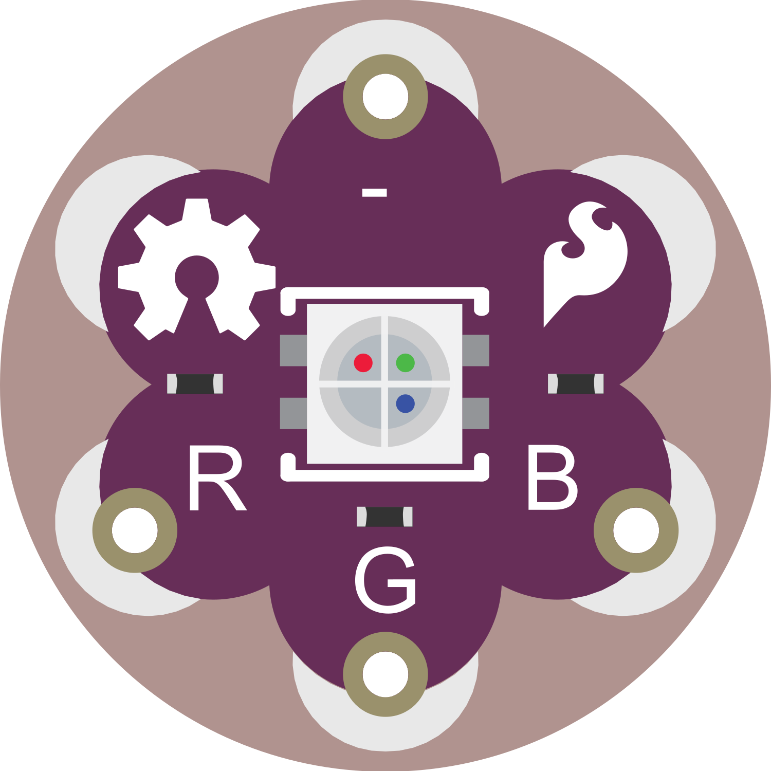
The LilyPad RGB LED is a versatile and compact electronic component designed for wearable projects. It integrates a tri-color (Red, Green, Blue) LED with a built-in current-limiting resistor, making it ideal for adding colorful lighting effects to textiles and other materials. With the ability to be sewn into fabric using conductive thread, the LilyPad RGB LED is perfect for fashion designers, hobbyists, and educators looking to incorporate interactive and illuminated elements into their designs.
Explore Projects Built with LilyPad RGB LED
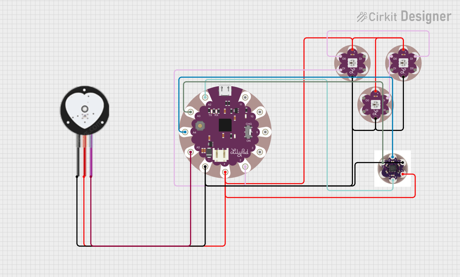
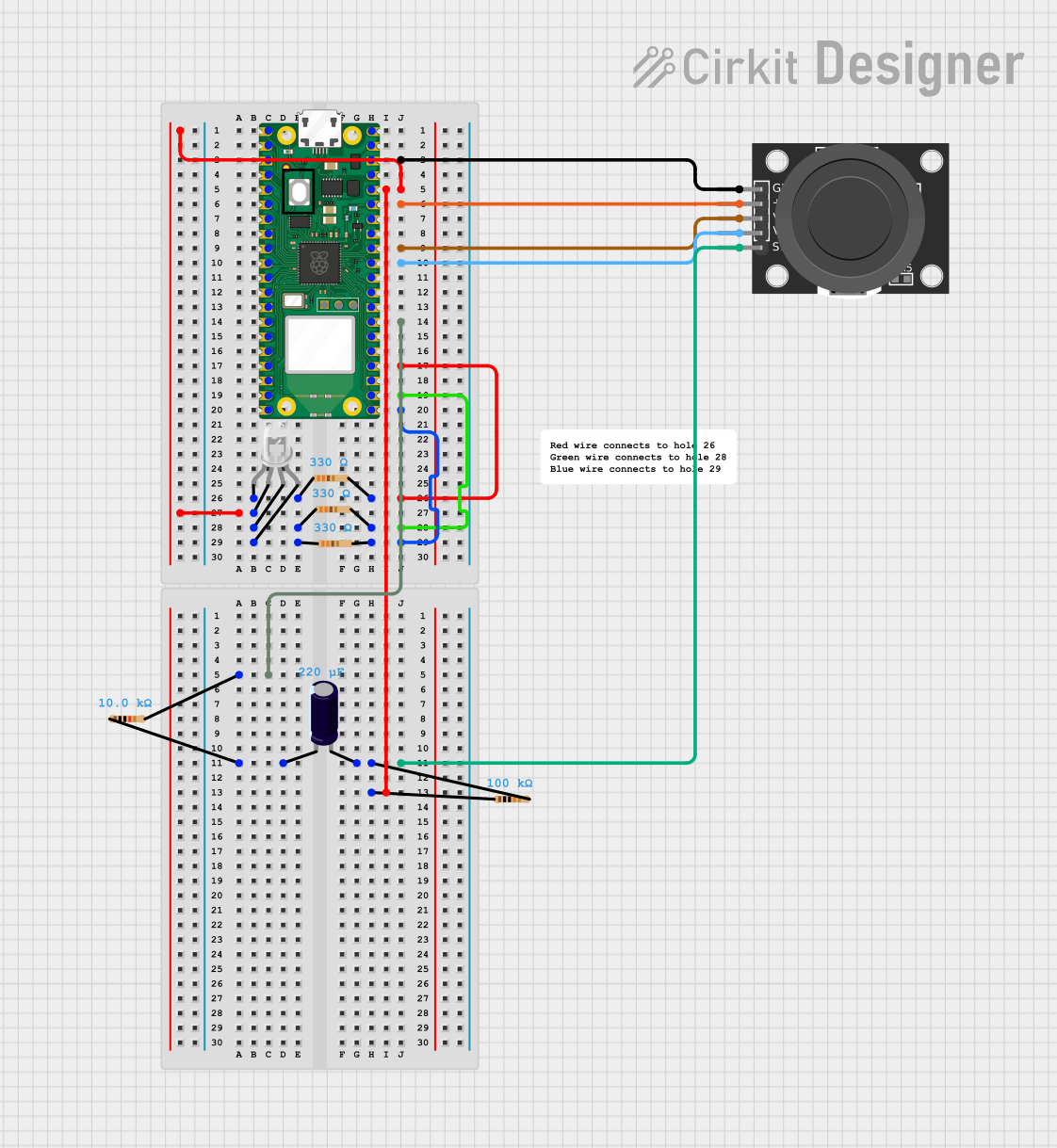
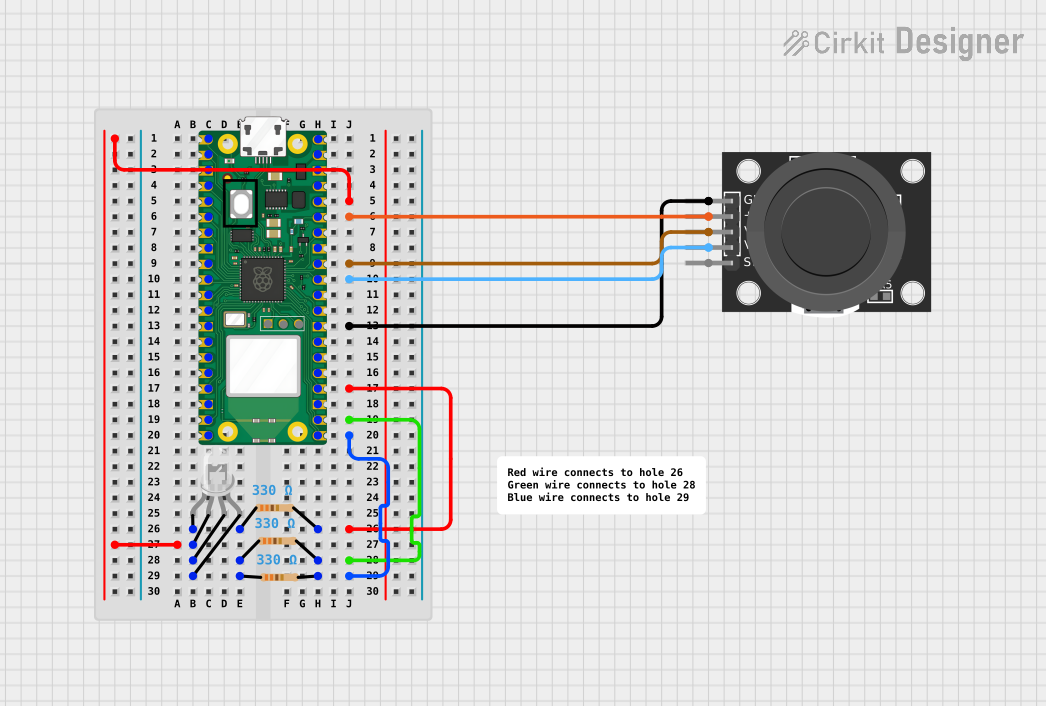
Explore Projects Built with LilyPad RGB LED
Common Applications and Use Cases
- Wearable electronics (e.g., smart clothing, accessories)
- Educational projects teaching basic electronics and programming
- Interactive textile projects
- Prototyping for smart garment technology
Technical Specifications
Key Technical Details
- Supply Voltage: 3.0V to 5.5V
- Current Draw: 20mA per LED at maximum brightness
- LED: RGB (Red, Green, Blue) LED
- Built-in Resistor: 150Ω for each LED color
Pin Configuration and Descriptions
| Pin Name | Description |
|---|---|
| + | Power supply (3.0V to 5.5V) |
| - | Ground |
| R | Control pin for the red LED |
| G | Control pin for the green LED |
| B | Control pin for the blue LED |
Usage Instructions
How to Use the LilyPad RGB LED in a Circuit
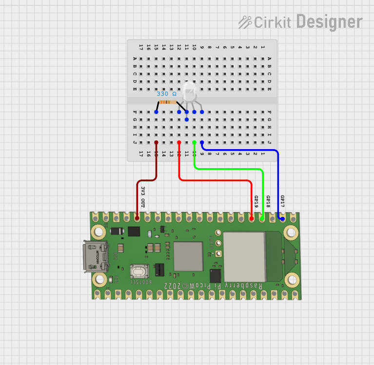
- Power Connection: Connect the '+' pin to a power supply between 3.0V and 5.5V, and the '-' pin to ground.
- Control Pins: Connect the 'R', 'G', and 'B' pins to digital output pins on a microcontroller, such as an Arduino UNO, to control the color of the LED.
- Programming: Use PWM (Pulse Width Modulation) to control the brightness of each color, allowing for color mixing to create a wide range of colors.
Important Considerations and Best Practices
- Ensure the power supply does not exceed 5.5V to prevent damage to the LED.
- Use current-limiting resistors if connecting to a power supply greater than 5.5V.
- Avoid excessive bending or pulling on the connections to prevent damage.
- When sewing with conductive thread, ensure there are no short circuits between the conductive traces.
Example Code for Arduino UNO
// Define the RGB LED pins
const int redPin = 9;   // R pin connected to digital pin 9
const int greenPin = 10; // G pin connected to digital pin 10
const int bluePin = 11;  // B pin connected to digital pin 11

void setup() {
  // Set the RGB LED pins as outputs
  pinMode(redPin, OUTPUT);
  pinMode(greenPin, OUTPUT);
  pinMode(bluePin, OUTPUT);
}

void loop() {
  // Set the color to purple
  analogWrite(redPin, 255);   // Set red brightness to maximum
  analogWrite(greenPin, 0);   // Turn off green
  analogWrite(bluePin, 255);  // Set blue brightness to maximum

  delay(1000); // Wait for 1 second

  // Set the color to yellow
  analogWrite(redPin, 255);   // Set red brightness to maximum
  analogWrite(greenPin, 255); // Set green brightness to maximum
  analogWrite(bluePin, 0);    // Turn off blue

  delay(1000); // Wait for 1 second
}
Troubleshooting and FAQs
Common Issues Users Might Face
- LED Not Lighting Up: Ensure that the power supply is correctly connected and within the specified voltage range. Check that the control pins are correctly connected to the microcontroller.
- Incorrect Colors: Verify that the control pins are connected to the correct pins on the microcontroller and that the PWM values in the code match the desired color.
- Dim LED: If the LED appears dim, check that the power supply is providing sufficient voltage and that the PWM values are set high enough.
Solutions and Tips for Troubleshooting
- Double-check all connections for loose threads or short circuits when using conductive thread.
- Use a multimeter to verify that the correct voltage is being supplied to the '+' and '-' pins.
- Ensure that the microcontroller's digital pins are configured correctly in the code.
FAQs
Q: Can I wash garments with the LilyPad RGB LED sewn in? A: It is not recommended to wash electronic components. Remove the component or protect it from water and moisture before washing.
Q: How many LilyPad RGB LEDs can I connect to a single microcontroller? A: The number depends on the number of available PWM pins on the microcontroller and the power supply's capacity. Ensure that the total current draw does not exceed the microcontroller's or power supply's limits.
Q: Can I use the LilyPad RGB LED with a battery? A: Yes, as long as the battery provides a voltage within the 3.0V to 5.5V range and can supply enough current for the desired number of LEDs.