How to Use ADS 1293: Examples, Pinouts, and Specs
Introduction
The ADS1293 is a low-power, 24-bit analog-to-digital converter (ADC) specifically designed for biopotential measurements, such as electrocardiogram (ECG) and electroencephalogram (EEG) applications. This highly integrated device features multiple channels, high precision, and programmable gain amplifiers (PGAs), making it ideal for medical devices, wearable health monitors, and other biopotential sensing applications. Its compact design and low power consumption make it particularly suitable for battery-powered devices.
Explore Projects Built with ADS 1293


Explore Projects Built with ADS 1293
Common Applications and Use Cases
- ECG monitoring in medical devices
- EEG systems for brain activity measurement
- Wearable health and fitness trackers
- Portable biopotential measurement systems
- Research and development in biomedical signal processing
Technical Specifications
Key Technical Details
- Resolution: 24-bit
- Number of Channels: 3 fully integrated channels
- Input Voltage Range: ±300 mV (programmable)
- Programmable Gain Amplifier (PGA) Gains: 1, 2, 3, 4, 6, 8, 12
- Sampling Rate: Up to 25.6 kSPS (kilosamples per second)
- Power Supply Voltage: 2.0 V to 3.6 V
- Power Consumption: 300 µW (typical at 2.6 V, 500 SPS)
- Communication Interface: SPI (Serial Peripheral Interface)
- Integrated Features: Lead-off detection, right-leg drive amplifier, and internal reference voltage
- Operating Temperature Range: -40°C to +85°C
- Package: 28-pin TSSOP (Thin Shrink Small Outline Package)
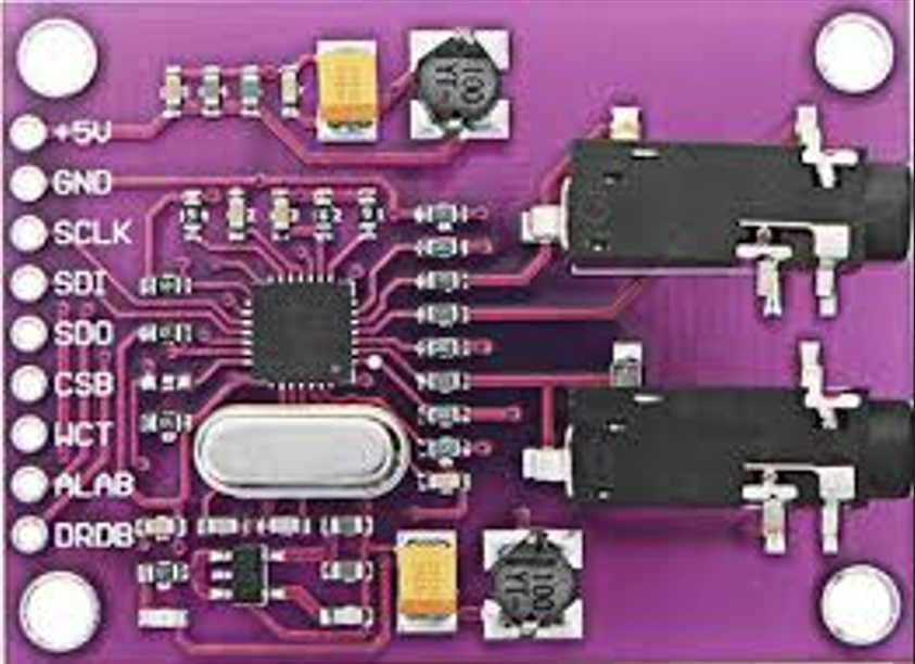
Pin Configuration and Descriptions
The ADS1293 comes in a 28-pin TSSOP package. Below is the pin configuration and description:
| Pin Number | Pin Name | Description |
|---|---|---|
| 1 | VDD | Positive power supply (2.0 V to 3.6 V). |
| 2 | GND | Ground reference for the device. |
| 3 | CS | Chip select for SPI communication. Active low. |
| 4 | SCLK | Serial clock input for SPI communication. |
| 5 | SDI | Serial data input for SPI communication. |
| 6 | SDO | Serial data output for SPI communication. |
| 7 | CLKSEL | Clock source selection pin. |
| 8 | RESET | Active-low reset pin. |
| 9 | DRDY | Data ready output. Indicates when new data is available. |
| 10-12 | IN1P, IN1N | Positive and negative inputs for Channel 1. |
| 13-15 | IN2P, IN2N | Positive and negative inputs for Channel 2. |
| 16-18 | IN3P, IN3N | Positive and negative inputs for Channel 3. |
| 19 | RLDOUT | Right-leg drive output. |
| 20 | RLDIN | Right-leg drive input. |
| 21 | VREFP | Positive reference voltage input. |
| 22 | VREFN | Negative reference voltage input. |
| 23 | CAP1 | External capacitor connection for internal reference. |
| 24 | CAP2 | External capacitor connection for internal reference. |
| 25 | CAP3 | External capacitor connection for internal reference. |
| 26 | GPIO1 | General-purpose input/output pin 1. |
| 27 | GPIO2 | General-purpose input/output pin 2. |
| 28 | GPIO3 | General-purpose input/output pin 3. |
Usage Instructions
How to Use the ADS1293 in a Circuit
- Power Supply: Connect the VDD pin to a stable power supply (2.0 V to 3.6 V) and GND to the ground.
- Input Signals: Connect biopotential electrodes to the input pins (e.g., IN1P/IN1N for Channel 1). Ensure proper filtering and impedance matching for accurate measurements.
- Reference Voltage: Use external capacitors on CAP1, CAP2, and CAP3 pins to stabilize the internal reference voltage.
- SPI Communication: Connect the SPI pins (CS, SCLK, SDI, SDO) to a microcontroller or processor for data acquisition and configuration.
- Clock Source: Select the clock source using the CLKSEL pin. An external clock or internal oscillator can be used.
- Right-Leg Drive: Use the RLDOUT and RLDIN pins for common-mode noise cancellation in ECG applications.
- Data Ready Signal: Monitor the DRDY pin to know when new data is available for reading.
Important Considerations and Best Practices
- Input Protection: Use appropriate protection circuits (e.g., resistors and diodes) to safeguard the inputs from overvoltage or electrostatic discharge (ESD).
- Filtering: Add low-pass filters to remove high-frequency noise from the input signals.
- Lead-Off Detection: Configure the lead-off detection feature to monitor electrode connections.
- Power Consumption: Optimize the sampling rate and PGA gain settings to minimize power consumption in battery-powered applications.
- PCB Layout: Ensure a proper ground plane and minimize noise coupling by keeping analog and digital traces separate.
Example Code for Arduino UNO
Below is an example of how to interface the ADS1293 with an Arduino UNO using SPI:
#include <SPI.h>

// Pin definitions
#define CS_PIN 10  // Chip select pin for ADS1293
#define DRDY_PIN 2 // Data ready pin for ADS1293

void setup() {
  // Initialize SPI communication
  SPI.begin();
  pinMode(CS_PIN, OUTPUT);
  pinMode(DRDY_PIN, INPUT);
  digitalWrite(CS_PIN, HIGH); // Set CS high initially

  // Configure ADS1293 (example: setting sampling rate and enabling channels)
  digitalWrite(CS_PIN, LOW); // Select the ADS1293
  SPI.transfer(0x01);        // Write to configuration register (example address)
  SPI.transfer(0x80);        // Example configuration value
  digitalWrite(CS_PIN, HIGH); // Deselect the ADS1293

  Serial.begin(9600);
}

void loop() {
  // Wait for data ready signal
  if (digitalRead(DRDY_PIN) == LOW) {
    digitalWrite(CS_PIN, LOW); // Select the ADS1293
    byte data = SPI.transfer(0x00); // Read data (example)
    digitalWrite(CS_PIN, HIGH); // Deselect the ADS1293

    // Print the received data
    Serial.println(data, HEX);
  }
}
Troubleshooting and FAQs
Common Issues and Solutions
No Data Output:
- Ensure the SPI connections (CS, SCLK, SDI, SDO) are correctly wired.
- Verify that the ADS1293 is powered and properly configured.
- Check the DRDY pin to confirm data availability.
High Noise in Measurements:
- Use proper shielding and grounding techniques to reduce noise.
- Add low-pass filters to the input signals.
- Verify the right-leg drive circuit is functioning correctly.
Incorrect Readings:
- Ensure the input signals are within the specified voltage range.
- Check the PGA gain settings and adjust them as needed.
- Verify the reference voltage is stable and properly configured.
Device Not Responding:
- Confirm the SPI clock frequency is within the supported range.
- Check the RESET pin to ensure the device is not held in reset state.
- Verify the power supply voltage is within the specified range.
FAQs
Q1: Can the ADS1293 be used for non-medical applications?
A1: Yes, the ADS1293 can be used for any application requiring high-precision, low-noise ADC measurements, such as industrial sensors or research projects.
Q2: What is the maximum sampling rate of the ADS1293?
A2: The maximum sampling rate is 25.6 kSPS, but lower rates can be configured to save power.
Q3: How do I detect if an electrode is disconnected?
A3: The ADS1293 includes a lead-off detection feature that can be configured to monitor electrode connections and alert the user if a disconnection occurs.
Q4: Can I use the ADS1293 with a 5V microcontroller?
A4: The ADS1293 operates at a maximum of 3.6 V. Use level shifters to interface with a 5V microcontroller.