How to Use CD4026 IC: Examples, Pinouts, and Specs
Introduction
The CD4026 IC, manufactured by IC, is a versatile decade counter and display driver designed to drive 7-segment displays directly. It is capable of counting from 0 to 9 and is widely used in applications requiring numerical displays, such as digital clocks, frequency counters, and event counters. The IC simplifies the process of interfacing a 7-segment display with minimal external components, making it a popular choice for both hobbyists and professionals.
Explore Projects Built with CD4026 IC

Explore Projects Built with CD4026 IC
Common Applications
- Digital clocks
- Frequency counters
- Event counters
- Scoreboards
- Timer circuits
- Simple numerical displays in embedded systems
Technical Specifications
The following table outlines the key technical specifications of the CD4026 IC:
| Parameter | Value |
|---|---|
| Supply Voltage (Vdd) | 3V to 15V |
| Maximum Input Voltage | Vdd |
| Output Current (per pin) | 10mA |
| Operating Temperature | -40°C to +85°C |
| Maximum Clock Frequency | 6 MHz (at 10V supply) |
| Power Dissipation | 500mW |
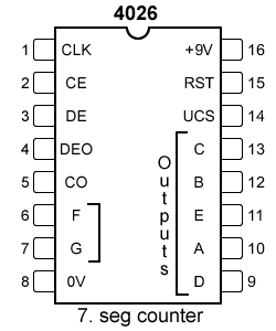
Pin Configuration and Descriptions
The CD4026 IC comes in a 16-pin Dual Inline Package (DIP). Below is the pin configuration and description:
| Pin Number | Pin Name | Description |
|---|---|---|
| 1 | Clock (CLK) | Input for clock signal; increments the counter on a rising edge. |
| 2 | Enable Input (EN) | Enables or disables the clock input. Active HIGH. |
| 3 | Zero Reset (RST) | Resets the counter to zero when HIGH. |
| 4 | Display Enable | Enables or disables the 7-segment display output. Active HIGH. |
| 5 | Segment 'e' | Output for segment 'e' of the 7-segment display. |
| 6 | Segment 'd' | Output for segment 'd' of the 7-segment display. |
| 7 | Segment 'c' | Output for segment 'c' of the 7-segment display. |
| 8 | Ground (GND) | Ground connection. |
| 9 | Segment 'b' | Output for segment 'b' of the 7-segment display. |
| 10 | Segment 'a' | Output for segment 'a' of the 7-segment display. |
| 11 | Segment 'f' | Output for segment 'f' of the 7-segment display. |
| 12 | Segment 'g' | Output for segment 'g' of the 7-segment display. |
| 13 | Display Enable Out | Output to cascade multiple CD4026 ICs. |
| 14 | Carry Out | Outputs a carry signal for cascading counters. |
| 15 | Clock Inhibit | Disables the clock input when HIGH. |
| 16 | Vdd | Positive power supply. |
Usage Instructions
How to Use the CD4026 IC in a Circuit
- Power Supply: Connect pin 16 (Vdd) to the positive supply voltage (3V to 15V) and pin 8 (GND) to ground.
- Clock Input: Provide a clock signal to pin 1 (CLK). Each rising edge of the clock signal increments the counter by 1.
- Reset Function: To reset the counter to zero, apply a HIGH signal to pin 3 (RST).
- 7-Segment Display: Connect the output pins (5 to 12) to the corresponding segments of a common cathode 7-segment display.
- Enable Display: Ensure pin 4 (Display Enable) is HIGH to activate the 7-segment display output.
- Cascading: Use pin 14 (Carry Out) and pin 13 (Display Enable Out) to cascade multiple CD4026 ICs for counting beyond 9.
Important Considerations
- Use current-limiting resistors (typically 330Ω to 1kΩ) between the segment outputs and the 7-segment display to prevent damage to the IC and display.
- Ensure the clock signal is clean and free of noise to avoid erratic counting.
- If cascading multiple ICs, ensure proper synchronization of the carry-out and clock signals.
Example: Interfacing CD4026 with Arduino UNO
Below is an example of how to use the CD4026 IC with an Arduino UNO to drive a 7-segment display:
// Define pin connections
#define CLK_PIN 2    // Arduino pin connected to CD4026 Clock (Pin 1)
#define RST_PIN 3    // Arduino pin connected to CD4026 Reset (Pin 3)
#define EN_PIN 4     // Arduino pin connected to CD4026 Enable (Pin 2)

void setup() {
  pinMode(CLK_PIN, OUTPUT);  // Set Clock pin as output
  pinMode(RST_PIN, OUTPUT);  // Set Reset pin as output
  pinMode(EN_PIN, OUTPUT);   // Set Enable pin as output

  digitalWrite(RST_PIN, LOW);  // Ensure Reset is LOW initially
  digitalWrite(EN_PIN, HIGH);  // Enable the CD4026 IC
}

void loop() {
  for (int i = 0; i < 10; i++) {  // Count from 0 to 9
    digitalWrite(CLK_PIN, HIGH);  // Generate a clock pulse
    delay(10);                    // Short delay
    digitalWrite(CLK_PIN, LOW);   // Complete the clock pulse
    delay(1000);                  // Wait 1 second before next count
  }

  digitalWrite(RST_PIN, HIGH);  // Reset the counter
  delay(10);                    // Short delay
  digitalWrite(RST_PIN, LOW);   // Complete the reset
}
Notes:
- Ensure the 7-segment display is properly connected to the CD4026 output pins.
- Adjust the delay values in the code to control the counting speed.
Troubleshooting and FAQs
Common Issues and Solutions
The 7-segment display does not light up:
- Ensure the Display Enable pin (pin 4) is HIGH.
- Check the connections between the CD4026 and the 7-segment display.
- Verify that current-limiting resistors are correctly installed.
Erratic counting or skipping numbers:
- Ensure the clock signal is clean and free of noise.
- Use a debouncing circuit or software debouncing if a mechanical switch is used as the clock source.
The counter does not reset:
- Verify that the Reset pin (pin 3) is momentarily set HIGH to reset the counter.
Cascading multiple ICs does not work:
- Check the connections between the Carry Out (pin 14) and the Clock input of the next IC.
- Ensure proper synchronization of the clock and carry signals.
FAQs
Q: Can I use a common anode 7-segment display with the CD4026?
A: No, the CD4026 is designed to drive common cathode 7-segment displays only.
Q: What is the maximum number of CD4026 ICs I can cascade?
A: Theoretically, you can cascade as many as needed, but practical limitations such as signal integrity and power supply constraints should be considered.
Q: Can the CD4026 count in reverse?
A: No, the CD4026 is a unidirectional counter and cannot count in reverse.
Q: What happens if the clock frequency exceeds the maximum limit?
A: The IC may fail to count correctly or may not function at all. Always ensure the clock frequency is within the specified range.