How to Use 4011: Examples, Pinouts, and Specs

Introduction
The 4011 IC is a fundamental component in digital electronics, consisting of four independent 2-input NAND gates in a single package. This versatile IC is used in various applications such as logic gate circuits, oscillators, and other digital systems where NAND logic is required. Its ability to perform the NAND operation, which is a universal logic gate, makes it a staple in digital circuit design.
Explore Projects Built with 4011
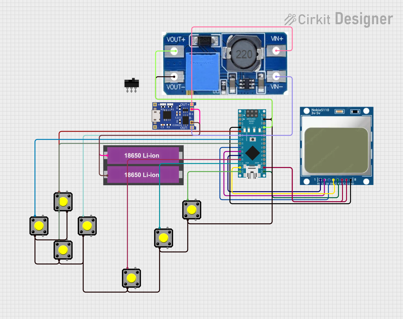

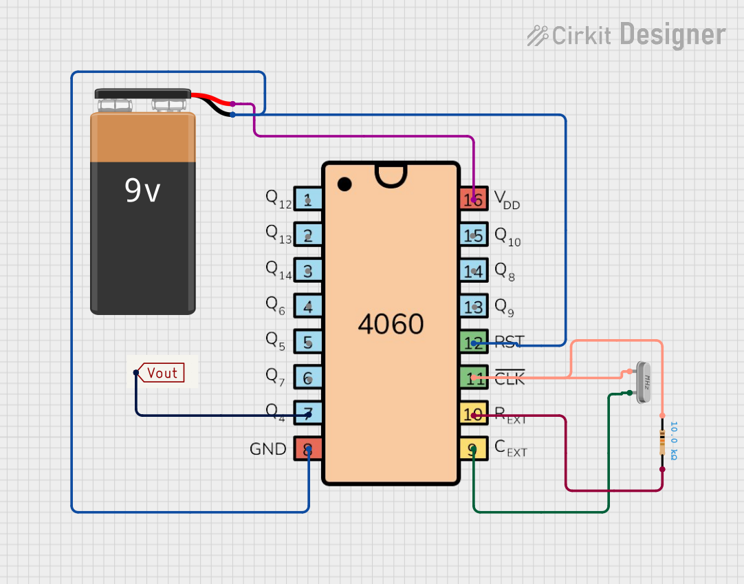
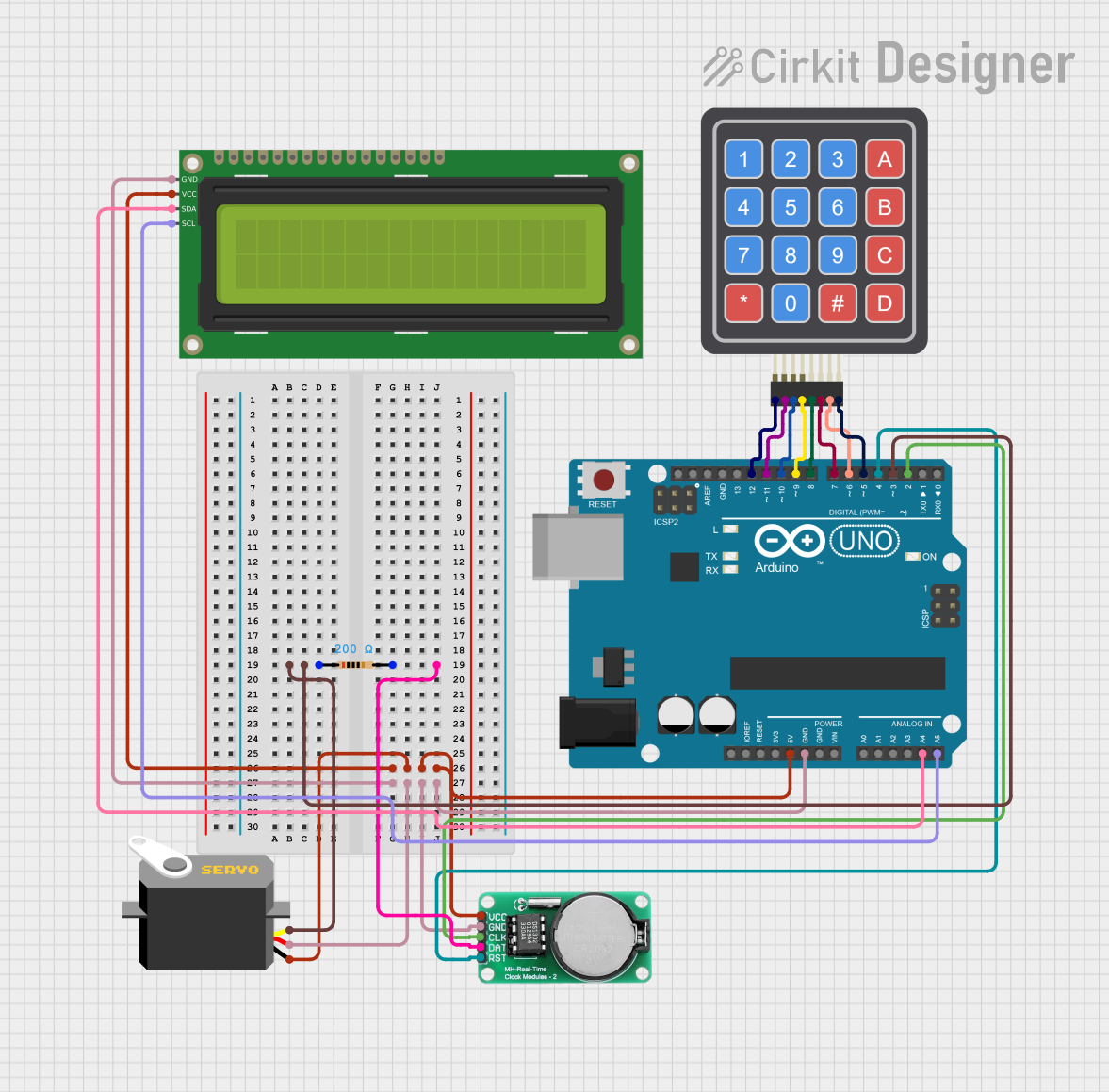
Explore Projects Built with 4011
Common Applications and Use Cases
- Digital logic circuits
- Signal gating
- Oscillator circuits
- Pulse generators
- Function generators
- Alarm systems
- Combination and sequential logic
Technical Specifications
Key Technical Details
- Operating Voltage Range: 3V to 15V
- High-level Input Voltage (V_IH): Minimum 3.15V (for V_DD = 5V)
- Low-level Input Voltage (V_IL): Maximum 1.35V (for V_DD = 5V)
- High-level Output Voltage (V_OH): Minimum 4.6V (for V_DD = 5V, I_O = -4.2 mA)
- Low-level Output Voltage (V_OL): Maximum 0.4V (for V_DD = 5V, I_O = 4.2 mA)
- Input Current (I_I): ±1 µA (for V_DD = 5V, V_I = V_SS or V_DD)
- Output Current (I_O): 4.2 mA (for V_DD = 5V)
- Power Dissipation (P_D): 500 mW
- Operating Temperature Range: -55°C to +125°C
Pin Configuration and Descriptions
| Pin Number | Description |
|---|---|
| 1 | Input A1 for Gate 1 |
| 2 | Input B1 for Gate 1 |
| 3 | Output Y1 for Gate 1 |
| 4 | Output Y2 for Gate 2 |
| 5 | Input A2 for Gate 2 |
| 6 | Input B2 for Gate 2 |
| 7 | Ground (0V) |
| 8 | Input A3 for Gate 3 |
| 9 | Input B3 for Gate 3 |
| 10 | Output Y3 for Gate 3 |
| 11 | Output Y4 for Gate 4 |
| 12 | Input A4 for Gate 4 |
| 13 | Input B4 for Gate 4 |
| 14 | Positive Supply Voltage (V_DD) |
Usage Instructions
How to Use the Component in a Circuit
Power Supply Connection: Connect pin 14 to the positive supply voltage (V_DD) within the range of 3V to 15V. Connect pin 7 to the ground (0V).
Input Signals: Apply the input signals to the respective A and B input pins for each gate. Ensure that the input voltage levels are compatible with the logic levels of the 4011 IC.
Output Connection: The output of each gate can be connected to other digital ICs, LEDs (with current-limiting resistors), or any suitable load within the output current rating.
Bypass Capacitor: Place a 0.1 µF ceramic bypass capacitor between V_DD and ground near the 4011 IC to filter out noise and provide a stable power supply.
Important Considerations and Best Practices
- Avoid leaving input pins floating as this can lead to unpredictable behavior. Use pull-up or pull-down resistors if necessary.
- Ensure that the total power dissipation does not exceed the maximum rating of 500 mW.
- Keep the output current within the specified limits to prevent damage to the IC.
- Use proper decoupling techniques to minimize the effects of switching noise.
Troubleshooting and FAQs
Common Issues Users Might Face
- Unstable Outputs: This can be caused by noise or a floating input. Ensure that all inputs are driven correctly and that a bypass capacitor is used.
- Excessive Power Consumption: Check for short circuits or incorrect supply voltage. Ensure that the IC is not being driven beyond its maximum ratings.
- No Output Signal: Verify that the supply voltage is within the specified range and that inputs are receiving the correct logic levels.
Solutions and Tips for Troubleshooting
- Always start by checking the power supply connections and input signals.
- Measure the voltage levels at the inputs and outputs to ensure they match expected logic levels.
- Replace the IC if it has been exposed to conditions beyond its maximum ratings, as it may have been damaged.
FAQs
Q: Can the 4011 IC be used to create other logic gates? A: Yes, by connecting the inputs and outputs in certain configurations, you can create other logic functions such as AND, OR, and NOT gates.
Q: Is it possible to use the 4011 IC at a voltage lower than 3V? A: Operating the 4011 below its minimum recommended voltage may result in improper functioning or no operation at all.
Q: Can I connect the outputs of two gates together? A: Directly connecting outputs can cause damage due to contention. Use proper techniques like open-collector configurations or external components to combine outputs safely.
Example Code for Arduino UNO
The following is an example of how to use the 4011 IC with an Arduino UNO to create a simple NAND gate operation.
// Define the input and output pins
const int inputPinA = 2;
const int inputPinB = 3;
const int outputPin = 13; // LED on Arduino board

void setup() {
  // Set the input and output pin modes
  pinMode(inputPinA, INPUT);
  pinMode(inputPinB, INPUT);
  pinMode(outputPin, OUTPUT);
}

void loop() {
  // Read the state of the input pins
  int stateA = digitalRead(inputPinA);
  int stateB = digitalRead(inputPinB);

  // Perform the NAND operation
  int nandResult = !(stateA && stateB);

  // Write the result to the output pin
  digitalWrite(outputPin, nandResult);

  // Delay for debounce
  delay(50);
}
Remember to connect the Arduino input pins to the corresponding inputs of one of the NAND gates on the 4011 IC and the output of that gate to the Arduino output pin. The LED on pin 13 will illuminate when either or both inputs are LOW, demonstrating the NAND operation.