How to Use RELAY SRD-05VDC-SL-C: Examples, Pinouts, and Specs
Introduction
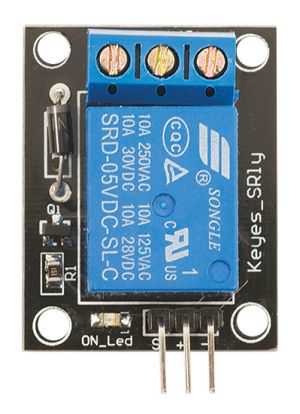
The SRD-05VDC-SL-C is a compact electromagnetic relay manufactured by SONGLE. It operates at a 5V DC input and is widely used in electronic circuits for switching applications. This relay features a Single Pole Double Throw (SPDT) configuration, enabling it to control high-voltage or high-current devices using a low-voltage control signal. Its versatility and reliability make it a popular choice for automation, home appliances, and IoT projects.
Explore Projects Built with RELAY SRD-05VDC-SL-C


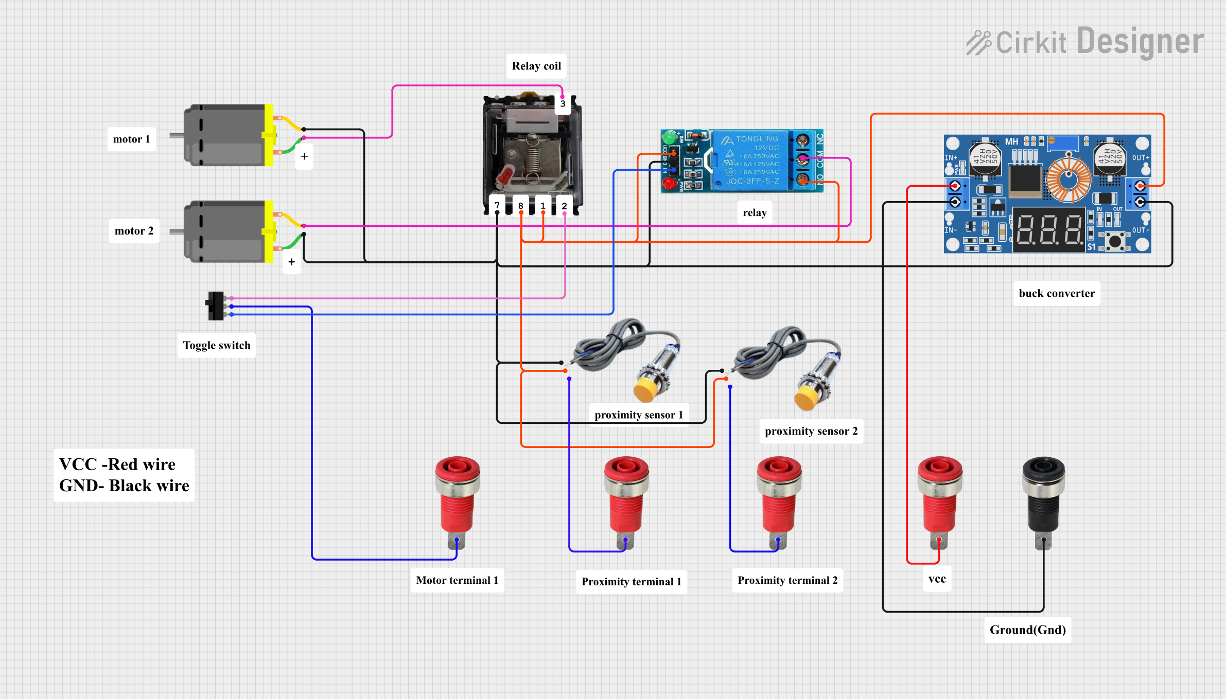
Explore Projects Built with RELAY SRD-05VDC-SL-C
Common Applications
- Home automation systems (e.g., controlling lights, fans, or appliances)
- Industrial control systems
- IoT projects for remote device control
- Motor control circuits
- Power supply switching
Technical Specifications
Below are the key technical details of the SRD-05VDC-SL-C relay:
| Parameter | Value |
|---|---|
| Manufacturer | SONGLE |
| Part Number | SRD-05VDC-SL-C |
| Coil Voltage | 5V DC |
| Coil Resistance | 70 Ω ±10% |
| Contact Configuration | SPDT (Single Pole Double Throw) |
| Contact Rating | 10A @ 250V AC / 10A @ 30V DC |
| Switching Voltage (Max) | 250V AC / 30V DC |
| Switching Current (Max) | 10A |
| Dielectric Strength | 500V AC (coil to contact) |
| Operating Temperature | -40°C to +85°C |
| Dimensions | 19mm x 15.5mm x 15mm |
Pin Configuration
The SRD-05VDC-SL-C relay has 5 pins, as described in the table below:
| Pin Number | Name | Description |
|---|---|---|
| 1 | Coil (+) | Positive terminal of the relay coil. Connect to a 5V DC control signal. |
| 2 | Coil (-) | Negative terminal of the relay coil. Connect to ground (GND). |
| 3 | Common (COM) | Common terminal for the relay's switching contacts. |
| 4 | Normally Open (NO) | Open when the relay is inactive; connects to COM when the relay is activated. |
| 5 | Normally Closed (NC) | Closed when the relay is inactive; disconnects from COM when the relay is activated. |
Usage Instructions
How to Use the SRD-05VDC-SL-C in a Circuit
- Power the Relay Coil: Connect the coil pins (1 and 2) to a 5V DC power source. Pin 1 should be connected to the positive terminal, and Pin 2 to ground.
- Control the Relay: Use a microcontroller (e.g., Arduino) or a transistor to control the relay coil. When the coil is energized, the relay switches from the NC contact to the NO contact.
- Connect the Load:
- Connect the device or circuit you want to control to the COM and NO pins if you want it to turn on when the relay is activated.
- Use the COM and NC pins if you want the device to turn off when the relay is activated.
- Add a Flyback Diode: Place a diode (e.g., 1N4007) across the coil terminals to protect the circuit from voltage spikes caused by the relay's inductive load.
Example Circuit with Arduino UNO
Below is an example of how to control the SRD-05VDC-SL-C relay using an Arduino UNO:
Circuit Connections
- Relay Pin 1 (Coil +): Connect to Arduino digital pin (e.g., D7) through a 1kΩ resistor.
- Relay Pin 2 (Coil -): Connect to Arduino GND.
- Relay COM Pin: Connect to one terminal of the load (e.g., a light bulb).
- Relay NO Pin: Connect to the power source for the load.
- Relay NC Pin: Leave unconnected (optional, depending on use case).
Arduino Code
// Define the pin connected to the relay
const int relayPin = 7;

void setup() {
  // Set the relay pin as an output
  pinMode(relayPin, OUTPUT);

  // Start with the relay off
  digitalWrite(relayPin, LOW);
}

void loop() {
  // Turn the relay on (activates the NO contact)
  digitalWrite(relayPin, HIGH);
  delay(1000); // Keep the relay on for 1 second

  // Turn the relay off (deactivates the NO contact)
  digitalWrite(relayPin, LOW);
  delay(1000); // Keep the relay off for 1 second
}
Important Considerations
- Power Supply: Ensure the relay coil is powered with a stable 5V DC source. Using a higher voltage may damage the relay.
- Isolation: For safety, use an optocoupler or transistor to isolate the control circuit from the relay.
- Load Ratings: Do not exceed the relay's maximum contact ratings (10A @ 250V AC or 10A @ 30V DC).
- Mounting: Secure the relay on a PCB or breadboard to prevent loose connections.
Troubleshooting and FAQs
Common Issues
Relay Not Switching:
- Cause: Insufficient voltage or current to the coil.
- Solution: Verify that the coil is receiving 5V DC and check the control circuit.
Load Not Turning On/Off:
- Cause: Incorrect wiring of the COM, NO, or NC pins.
- Solution: Double-check the connections and ensure the load is properly connected.
Relay Buzzing Noise:
- Cause: Unstable power supply or insufficient current to the coil.
- Solution: Use a stable 5V DC power source and ensure the control circuit can supply enough current.
Overheating:
- Cause: Exceeding the relay's contact ratings.
- Solution: Ensure the load does not exceed 10A or the specified voltage limits.
FAQs
Q1: Can I use the SRD-05VDC-SL-C with a 3.3V microcontroller?
A1: Yes, but you will need a transistor or relay driver circuit to step up the control signal to 5V.
Q2: Is the relay suitable for switching DC motors?
A2: Yes, as long as the motor's voltage and current are within the relay's contact ratings. Use a flyback diode to protect the circuit from voltage spikes.
Q3: Can I use the relay for high-frequency switching?
A3: No, the SRD-05VDC-SL-C is not designed for high-frequency switching. It is best suited for low-frequency applications.
Q4: What is the lifespan of the relay?
A4: The relay has a mechanical lifespan of approximately 10 million operations and an electrical lifespan of around 100,000 operations under rated load conditions.