How to Use AC to DC converter PM01 5V: Examples, Pinouts, and Specs
Documentation for AC to DC Converter: Hi-Link PM01 5V
1. Introduction
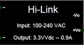
The Hi-Link PM01 5V is a compact and efficient AC to DC converter designed to provide a regulated 5V DC output from an AC input. This module is widely used in electronic projects and industrial applications where a stable 5V power supply is required. Its small size, high efficiency, and ease of integration make it a popular choice for powering microcontrollers, sensors, and other low-power devices.
Common Applications:
- Powering microcontrollers (e.g., Arduino, ESP32, Raspberry Pi peripherals)
- IoT devices and smart home systems
- Industrial control systems
- LED lighting and displays
- Battery charging circuits
- General-purpose low-power DC applications
2. Technical Specifications
The following table outlines the key technical details of the Hi-Link PM01 5V module:
| Parameter | Value |
|---|---|
| Manufacturer | Hi-Link |
| Part Number | PM01 |
| Input Voltage Range | 90V AC to 264V AC |
| Output Voltage | 5V DC |
| Output Current | 0.6A (600mA) |
| Output Power | 3W |
| Efficiency | ≥ 70% |
| Frequency Range | 47Hz to 63Hz |
| Operating Temperature | -25°C to +70°C |
| Storage Temperature | -40°C to +85°C |
| Dimensions | 35mm x 18mm x 15mm |
| Weight | ~10g |
| Isolation Voltage | 3000V AC |
| Safety Standards | CE, RoHS |
Pin Configuration and Descriptions
The Hi-Link PM01 5V module has six pins, as described in the table below:
| Pin Number | Pin Name | Description |
|---|---|---|
| 1 | AC(L) | AC live input (connect to the live wire of AC mains) |
| 2 | AC(N) | AC neutral input (connect to the neutral wire) |
| 3 | NC | Not connected (leave unconnected) |
| 4 | +5V | Regulated 5V DC output |
| 5 | GND | Ground (DC output ground) |
| 6 | NC | Not connected (leave unconnected) |
3. Usage Instructions
How to Use the Hi-Link PM01 5V in a Circuit
Input Connection:
- Connect the AC(L) pin to the live wire of the AC mains.
- Connect the AC(N) pin to the neutral wire of the AC mains.
- Ensure proper insulation and safety precautions when working with AC mains.
Output Connection:
- Connect the +5V pin to the positive terminal of your load or circuit.
- Connect the GND pin to the ground terminal of your load or circuit.
Mounting:
- The module can be soldered onto a PCB or mounted using connectors.
- Ensure adequate spacing between the AC and DC sides to prevent short circuits.
Safety Considerations:
- Always use the module within its specified input voltage range (90V AC to 264V AC).
- Avoid touching the module while it is powered to prevent electric shock.
- Use a fuse or circuit breaker on the AC input for added protection.
Best Practices:
- Use a capacitor (e.g., 470µF) on the output to stabilize the voltage if your load is sensitive to fluctuations.
- Place the module in a well-ventilated area to prevent overheating.
- Avoid exposing the module to moisture or extreme temperatures.
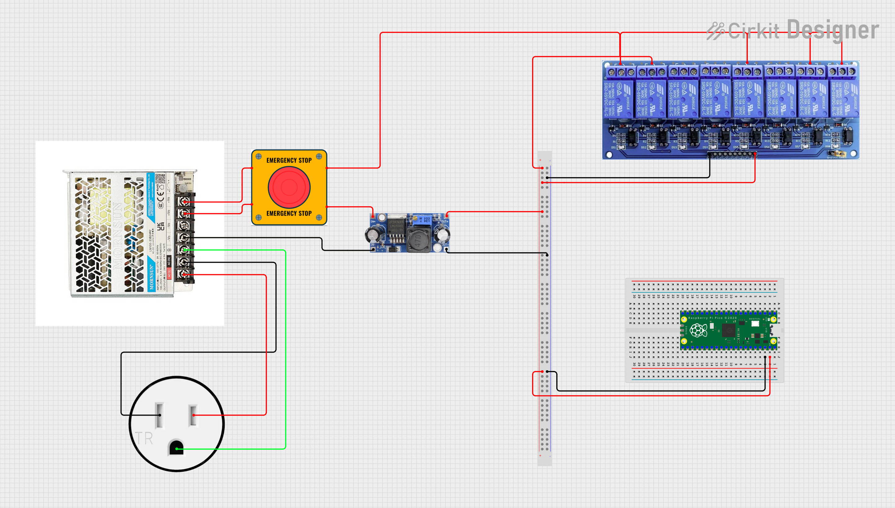
4. Example Application with Arduino UNO
The Hi-Link PM01 5V can be used to power an Arduino UNO directly from an AC mains supply. Below is an example circuit and code to demonstrate its usage.
Circuit Diagram:
- Connect the AC(L) and AC(N) pins of the PM01 to the AC mains (use proper insulation).
- Connect the +5V pin of the PM01 to the 5V pin of the Arduino UNO.
- Connect the GND pin of the PM01 to the GND pin of the Arduino UNO.
Arduino Code Example:
The following code blinks an LED connected to pin 13 of the Arduino UNO:
// Blink an LED connected to pin 13 of the Arduino UNO
// Ensure the Hi-Link PM01 5V is properly connected to power the Arduino

void setup() {
  pinMode(13, OUTPUT); // Set pin 13 as an output pin
}

void loop() {
  digitalWrite(13, HIGH); // Turn the LED on
  delay(1000);            // Wait for 1 second
  digitalWrite(13, LOW);  // Turn the LED off
  delay(1000);            // Wait for 1 second
}
5. Troubleshooting and FAQs
Common Issues and Solutions:
| Issue | Possible Cause | Solution |
|---|---|---|
| No output voltage | Incorrect AC input connection | Verify AC(L) and AC(N) connections. |
| Output voltage fluctuates | Insufficient load or unstable input voltage | Add a capacitor (e.g., 470µF) to the output. |
| Module overheats | Overloading or poor ventilation | Reduce load or improve ventilation. |
| Arduino does not power on | Loose connections or insufficient current | Check connections and ensure load is ≤ 600mA. |
Frequently Asked Questions:
Can the PM01 be used with 12V DC input?
- No, the PM01 is designed for AC input only (90V AC to 264V AC).
Is the PM01 safe to use with household AC mains?
- Yes, but ensure proper insulation and safety precautions when handling AC mains.
What is the maximum load the PM01 can handle?
- The PM01 can provide up to 600mA (3W) at 5V DC.
Can I use the PM01 to power multiple devices?
- Yes, as long as the total current draw does not exceed 600mA.
Does the PM01 require a heatsink?
- No, the PM01 is designed to operate without a heatsink under normal conditions.
6. Conclusion
The Hi-Link PM01 5V is a reliable and efficient AC to DC converter suitable for a wide range of applications. Its compact size, ease of use, and stable 5V output make it an excellent choice for powering low-power electronic devices. By following the usage instructions and safety guidelines provided in this documentation, users can integrate the PM01 into their projects with confidence.
Explore Projects Built with AC to DC converter PM01 5V


Explore Projects Built with AC to DC converter PM01 5V