How to Use ESP32-D: Examples, Pinouts, and Specs
Introduction
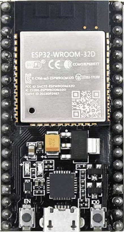
The ESP32-D, manufactured by HiLetgo, is a versatile and powerful microcontroller designed for Internet of Things (IoT) applications. It integrates Wi-Fi and Bluetooth capabilities, enabling seamless wireless communication. With its dual-core processor, extensive GPIO pins, and support for multiple communication protocols, the ESP32-D is ideal for smart devices, home automation, wearable electronics, and industrial IoT projects.
Explore Projects Built with ESP32-D


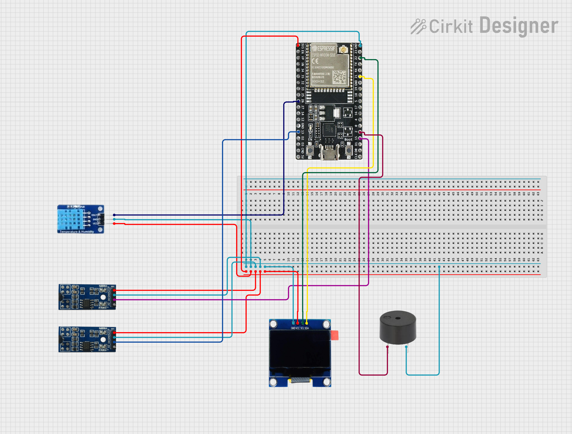
Explore Projects Built with ESP32-D
Common Applications
- Smart home devices (e.g., smart lights, thermostats)
- Wearable technology
- Industrial automation and monitoring
- Wireless sensor networks
- Robotics and drones
- IoT prototyping and development
Technical Specifications
The ESP32-D offers robust performance and flexibility for a wide range of applications. Below are its key technical details:
Key Technical Details
| Parameter | Specification |
|---|---|
| Manufacturer | HiLetgo |
| Microcontroller | Tensilica Xtensa LX6 Dual-Core |
| Clock Speed | Up to 240 MHz |
| Flash Memory | 4 MB (varies by model) |
| SRAM | 520 KB |
| Wi-Fi | 802.11 b/g/n (2.4 GHz) |
| Bluetooth | v4.2 BR/EDR and BLE |
| Operating Voltage | 3.3V |
| Input Voltage Range | 5V (via USB) or 3.3V (via pins) |
| GPIO Pins | 34 |
| ADC Channels | 18 (12-bit resolution) |
| DAC Channels | 2 |
| Communication Protocols | UART, SPI, I2C, I2S, CAN, PWM |
| Power Consumption | Ultra-low power (varies by mode) |
| Operating Temperature | -40°C to +85°C |
Pin Configuration and Descriptions
The ESP32-D features a variety of pins for different functionalities. Below is a summary of the pin configuration:
| Pin Name | Functionality | Description |
|---|---|---|
| GPIO0 | Input/Output, Boot Mode Selection | Used for boot mode selection during startup. |
| GPIO1 | UART TX | Transmit pin for UART communication. |
| GPIO2 | Input/Output, ADC, PWM | General-purpose pin with ADC and PWM support. |
| GPIO3 | UART RX | Receive pin for UART communication. |
| GPIO4 | Input/Output, ADC, PWM | General-purpose pin with ADC and PWM support. |
| GPIO5 | Input/Output, ADC, PWM | General-purpose pin with ADC and PWM support. |
| GPIO12 | Input/Output, ADC, PWM, Boot Mode | Can be used for boot mode selection. |
| GPIO13 | Input/Output, ADC, PWM | General-purpose pin with ADC and PWM support. |
| GPIO14 | Input/Output, ADC, PWM | General-purpose pin with ADC and PWM support. |
| GPIO15 | Input/Output, ADC, PWM | General-purpose pin with ADC and PWM support. |
| GPIO16 | Input/Output | General-purpose pin. |
| GPIO17 | Input/Output | General-purpose pin. |
Note: Not all GPIO pins support ADC, PWM, or other advanced features. Refer to the ESP32-D datasheet for a complete pinout and functionality details.
Usage Instructions
The ESP32-D is easy to integrate into a variety of projects. Below are the steps and best practices for using the component effectively.
How to Use the ESP32-D in a Circuit
Powering the ESP32-D:
- Use a 5V USB connection or supply 3.3V directly to the 3.3V pin.
- Ensure the power source can provide sufficient current (at least 500 mA).
Connecting to GPIO Pins:
- Use GPIO pins for input/output operations.
- Avoid using GPIO0, GPIO2, and GPIO12 for general purposes during boot, as they affect boot mode.
Programming the ESP32-D:
- Install the Arduino IDE or ESP-IDF (Espressif IoT Development Framework).
- Add the ESP32 board package to the Arduino IDE via the Board Manager.
- Connect the ESP32-D to your computer using a USB cable.
Uploading Code:
- Select the correct board and port in the Arduino IDE.
- Write or load your code and click the upload button.
Example Code for Arduino UNO Integration
The following example demonstrates how to blink an LED connected to GPIO2 of the ESP32-D:
// Blink an LED connected to GPIO2 on the ESP32-D
// Ensure the LED's anode is connected to GPIO2 and cathode to GND.

#define LED_PIN 2  // Define the GPIO pin for the LED

void setup() {
  pinMode(LED_PIN, OUTPUT);  // Set GPIO2 as an output pin
}

void loop() {
  digitalWrite(LED_PIN, HIGH);  // Turn the LED on
  delay(1000);                  // Wait for 1 second
  digitalWrite(LED_PIN, LOW);   // Turn the LED off
  delay(1000);                  // Wait for 1 second
}
Best Practices
- Use level shifters when interfacing with 5V logic devices, as the ESP32-D operates at 3.3V logic levels.
- Avoid connecting high-current loads directly to GPIO pins; use transistors or relays instead.
- Use decoupling capacitors near the power pins to reduce noise and improve stability.
Troubleshooting and FAQs
Common Issues and Solutions
ESP32-D Not Detected by Computer:
- Ensure the USB cable is functional and supports data transfer.
- Install the correct USB-to-serial driver for your operating system.
Code Upload Fails:
- Check that the correct board and port are selected in the Arduino IDE.
- Press and hold the "BOOT" button on the ESP32-D while uploading the code.
Wi-Fi Connection Issues:
- Verify the SSID and password in your code.
- Ensure the Wi-Fi network operates on the 2.4 GHz band (not 5 GHz).
Random Resets or Instability:
- Check the power supply for sufficient current and stable voltage.
- Avoid using GPIO0, GPIO2, or GPIO12 improperly during boot.
FAQs
Q: Can the ESP32-D operate on battery power?
A: Yes, the ESP32-D can be powered by a 3.7V LiPo battery with a suitable voltage regulator.
Q: How do I use Bluetooth on the ESP32-D?
A: Use the Arduino IDE or ESP-IDF to write Bluetooth code. The ESP32-D supports both Bluetooth Classic and BLE.
Q: What is the maximum range of the ESP32-D's Wi-Fi?
A: The range depends on environmental factors but typically extends up to 100 meters in open spaces.
Q: Can I use the ESP32-D with sensors and modules?
A: Yes, the ESP32-D supports I2C, SPI, UART, and other protocols, making it compatible with a wide range of sensors and modules.
By following this documentation, you can effectively utilize the ESP32-D in your IoT and automation projects.