Cirkit Designer Logo
Cirkit Designer
Your all-in-one circuit design IDE
Home / 
Component Documentation

How to Use Serial WiFi Module: Examples, Pinouts, and Specs

Image of Serial WiFi Module
Cirkit Designer LogoDesign with Serial WiFi Module in Cirkit Designer

Introduction

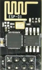
A Serial WiFi Module enables wireless communication in devices by connecting to WiFi networks, allowing for data transmission and reception over the internet. It is commonly used in IoT (Internet of Things) applications, home automation, and wireless data logging. The module typically interfaces with microcontrollers via serial communication protocols such as UART, making it easy to integrate into embedded systems.

Explore Projects Built with Serial WiFi Module

Use Cirkit Designer to design, explore, and prototype these projects online. Some projects support real-time simulation. Click "Open Project" to start designing instantly!
Arduino UNO and LoRa SX1278 Wireless Communication Module
Image of LoRa_wiring: A project utilizing Serial WiFi Module in a practical application
This circuit connects an Arduino UNO with a LoRa Ra-02 SX1278 module to enable long-range communication capabilities. The Arduino is configured to interface with the LoRa module via SPI (Serial Peripheral Interface), using digital pins D13 (SCK), D12 (MISO), D11 (MOSI), and D10 (NSS) for the clock, master-in-slave-out, master-out-slave-in, and slave select functions, respectively. Additional connections include a reset line to D9 and an interrupt line to D4, which are typically used for module reset and interrupt-driven event handling.
Cirkit Designer LogoOpen Project in Cirkit Designer
ESP8266 NodeMCU with LoRa and RS-485 Communication and Ethernet Connectivity
Image of Wiring Diagram LoRa: A project utilizing Serial WiFi Module in a practical application
This circuit serves as a multi-protocol communication hub featuring two ESP8266 NodeMCUs for processing, each connected to a LoRa Ra-02 SX1278 for long-range wireless communication. One NodeMCU is also connected to an RS-485 module for serial communication and a W5500 Ethernet module for network connectivity, with MB102 modules supplying power.
Cirkit Designer LogoOpen Project in Cirkit Designer
Arduino Nano and LoRa SX1278 Wireless Communication Module
Image of CSE216L Project Livestock Health Monitoring Secondary Circuit: A project utilizing Serial WiFi Module in a practical application
This circuit consists of an Arduino Nano microcontroller connected to a LoRa Ra-02 SX1278 module, enabling wireless communication. The Arduino handles the SPI communication with the LoRa module, with connections for SCK, MISO, MOSI, NSS, and RST, as well as power and ground connections. This setup is typically used for long-range, low-power wireless data transmission.
Cirkit Designer LogoOpen Project in Cirkit Designer
ESP8266 NodeMCU with LoRa and RS-485 Communication Interface
Image of RS485 Serial USB: A project utilizing Serial WiFi Module in a practical application
This circuit features two ESP8266 NodeMCU microcontrollers, each interfaced with a LoRa Ra-02 SX1278 module for long-range wireless communication, and an RS-485 module for wired serial communication. The ESP8266 microcontrollers are responsible for handling the communication protocols and data processing. Power is supplied to the microcontrollers via an MB102 Breadboard Power Supply Module, which provides both 3.3V and 5V outputs.
Cirkit Designer LogoOpen Project in Cirkit Designer

Explore Projects Built with Serial WiFi Module

Use Cirkit Designer to design, explore, and prototype these projects online. Some projects support real-time simulation. Click "Open Project" to start designing instantly!
Image of LoRa_wiring: A project utilizing Serial WiFi Module in a practical application
Arduino UNO and LoRa SX1278 Wireless Communication Module
This circuit connects an Arduino UNO with a LoRa Ra-02 SX1278 module to enable long-range communication capabilities. The Arduino is configured to interface with the LoRa module via SPI (Serial Peripheral Interface), using digital pins D13 (SCK), D12 (MISO), D11 (MOSI), and D10 (NSS) for the clock, master-in-slave-out, master-out-slave-in, and slave select functions, respectively. Additional connections include a reset line to D9 and an interrupt line to D4, which are typically used for module reset and interrupt-driven event handling.
Cirkit Designer LogoOpen Project in Cirkit Designer
Image of Wiring Diagram LoRa: A project utilizing Serial WiFi Module in a practical application
ESP8266 NodeMCU with LoRa and RS-485 Communication and Ethernet Connectivity
This circuit serves as a multi-protocol communication hub featuring two ESP8266 NodeMCUs for processing, each connected to a LoRa Ra-02 SX1278 for long-range wireless communication. One NodeMCU is also connected to an RS-485 module for serial communication and a W5500 Ethernet module for network connectivity, with MB102 modules supplying power.
Cirkit Designer LogoOpen Project in Cirkit Designer
Image of CSE216L Project Livestock Health Monitoring Secondary Circuit: A project utilizing Serial WiFi Module in a practical application
Arduino Nano and LoRa SX1278 Wireless Communication Module
This circuit consists of an Arduino Nano microcontroller connected to a LoRa Ra-02 SX1278 module, enabling wireless communication. The Arduino handles the SPI communication with the LoRa module, with connections for SCK, MISO, MOSI, NSS, and RST, as well as power and ground connections. This setup is typically used for long-range, low-power wireless data transmission.
Cirkit Designer LogoOpen Project in Cirkit Designer
Image of RS485 Serial USB: A project utilizing Serial WiFi Module in a practical application
ESP8266 NodeMCU with LoRa and RS-485 Communication Interface
This circuit features two ESP8266 NodeMCU microcontrollers, each interfaced with a LoRa Ra-02 SX1278 module for long-range wireless communication, and an RS-485 module for wired serial communication. The ESP8266 microcontrollers are responsible for handling the communication protocols and data processing. Power is supplied to the microcontrollers via an MB102 Breadboard Power Supply Module, which provides both 3.3V and 5V outputs.
Cirkit Designer LogoOpen Project in Cirkit Designer

Common Applications and Use Cases

  • IoT devices for remote monitoring and control
  • Home automation systems
  • Wireless data logging and telemetry
  • Smart appliances
  • Industrial automation and monitoring
  • Wireless sensor networks

Technical Specifications

Below are the general technical specifications for a typical Serial WiFi Module (e.g., ESP8266-based modules):

Parameter Value
Operating Voltage 3.0V - 3.6V
Communication Protocol UART (Serial)
WiFi Standard IEEE 802.11 b/g/n
Frequency Band 2.4 GHz
Data Rate Up to 72.2 Mbps
Power Consumption 15 µA (Deep Sleep), ~70 mA (Active TX/RX)
Operating Temperature -40°C to 125°C
Flash Memory 512 KB to 4 MB (varies by model)

Pin Configuration and Descriptions

The pinout for a typical Serial WiFi Module (e.g., ESP8266) is as follows:

Pin Name Description
VCC Power supply input (3.3V)
GND Ground
TX UART Transmit pin (connects to RX of microcontroller)
RX UART Receive pin (connects to TX of microcontroller)
CH_PD/EN Chip enable (active HIGH, connect to 3.3V)
GPIO0 General-purpose I/O pin, also used for boot mode
GPIO2 General-purpose I/O pin
RST Reset pin (active LOW)

Note: Ensure the module is powered with 3.3V. Supplying higher voltages (e.g., 5V) can damage the module.

Usage Instructions

How to Use the Component in a Circuit

  1. Power Supply: Connect the VCC pin to a 3.3V power source and GND to ground.
  2. Serial Communication: Connect the TX pin of the module to the RX pin of the microcontroller and the RX pin of the module to the TX pin of the microcontroller.
  3. Enable Pin: Connect the CH_PD/EN pin to 3.3V to enable the module.
  4. Reset: Optionally, connect the RST pin to a push-button for manual resets.
  5. Boot Mode: For programming, GPIO0 may need to be pulled LOW during reset.

Important Considerations and Best Practices

  • Use a level shifter or voltage divider if your microcontroller operates at 5V logic levels to avoid damaging the module.
  • Ensure a stable power supply with sufficient current (at least 300 mA) to avoid unexpected resets.
  • Use decoupling capacitors (e.g., 10 µF and 0.1 µF) near the VCC pin to filter noise.
  • Place the module away from sources of electromagnetic interference (EMI) for optimal WiFi performance.

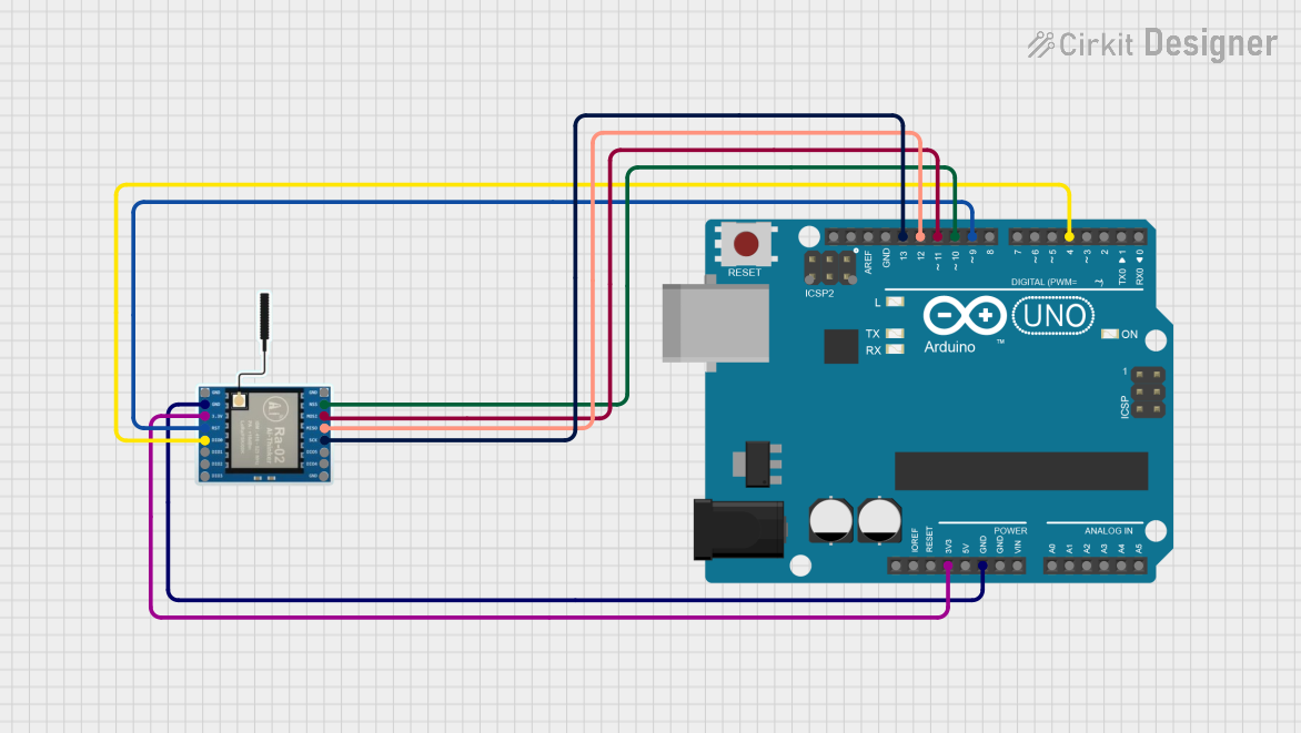
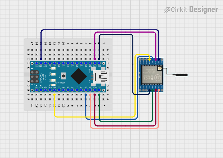
Example: Connecting to an Arduino UNO

Below is an example of how to use a Serial WiFi Module with an Arduino UNO to connect to a WiFi network and send data to a server.

Circuit Diagram

  • Connect the module's TX pin to Arduino's RX (pin 0).
  • Connect the module's RX pin to Arduino's TX (pin 1) through a voltage divider.
  • Connect VCC to 3.3V and GND to ground.
  • Connect CH_PD/EN to 3.3V.

Arduino Code

#include <SoftwareSerial.h>

// Define RX and TX pins for software serial communication
SoftwareSerial wifi(2, 3); // RX = pin 2, TX = pin 3

void setup() {
  Serial.begin(9600); // Start serial communication with the PC
  wifi.begin(9600);   // Start serial communication with the WiFi module

  Serial.println("Initializing WiFi Module...");
  wifi.println("AT"); // Send AT command to check communication
  delay(1000);

  // Connect to WiFi network
  wifi.println("AT+CWJAP=\"YourSSID\",\"YourPassword\""); 
  delay(5000); // Wait for connection to establish

  Serial.println("WiFi Module Initialized.");
}

void loop() {
  // Send data to a server
  wifi.println("AT+CIPSTART=\"TCP\",\"example.com\",80"); // Connect to server
  delay(2000);

  wifi.println("AT+CIPSEND=18"); // Specify data length
  delay(1000);

  wifi.println("GET / HTTP/1.1"); // Send HTTP GET request
  wifi.println("Host: example.com");
  wifi.println();
  delay(2000);

  // Read response from the server
  while (wifi.available()) {
    char c = wifi.read();
    Serial.print(c);
  }
}

Note: Replace YourSSID and YourPassword with your WiFi network credentials. Replace example.com with the server address you want to connect to.

Troubleshooting and FAQs

Common Issues and Solutions

  1. Module Not Responding to AT Commands

    • Ensure the module is powered with 3.3V and the CH_PD/EN pin is connected to 3.3V.
    • Check the serial communication baud rate. Some modules default to 115200 baud.
  2. WiFi Connection Fails

    • Verify the SSID and password are correct.
    • Ensure the WiFi network is within range and supports 2.4 GHz.
  3. Frequent Resets or Unstable Operation

    • Check the power supply for sufficient current and stability.
    • Add decoupling capacitors near the module's VCC pin.
  4. No Data Received from Server

    • Verify the server address and port are correct.
    • Check the server's firewall or access restrictions.

FAQs

Q: Can I use the module with a 5V microcontroller?
A: Yes, but you must use a level shifter or voltage divider for the RX pin to avoid damage.

Q: How do I update the firmware of the module?
A: Use a USB-to-serial adapter and the manufacturer's firmware update tool. Follow the specific instructions for your module.

Q: Can the module operate in standalone mode?
A: Yes, some modules (e.g., ESP8266) can be programmed directly using the Arduino IDE or other tools to operate without an external microcontroller.