Cirkit Designer Logo
Cirkit Designer
Your all-in-one circuit design IDE
Home / 
Component Documentation

How to Use XYS3580: Examples, Pinouts, and Specs
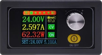
Image of XYS3580
Cirkit Designer LogoDesign with XYS3580 in Cirkit Designer

Introduction

The XYS3580 is a high-power Schottky diode designed for radio frequency (RF) applications. Schottky diodes are known for their low forward voltage drop and fast switching speed, making them ideal for high-frequency applications. The XYS3580 is commonly used in RF mixers, detectors, power rectifiers, and as a clamping diode to protect sensitive RF components from static discharge and other transient voltage spikes.

Explore Projects Built with XYS3580

Use Cirkit Designer to design, explore, and prototype these projects online. Some projects support real-time simulation. Click "Open Project" to start designing instantly!
Satellite-Based Timing and Navigation System with SDR and Atomic Clock Synchronization
Image of GPS 시스템 측정 구성도_Confirm: A project utilizing XYS3580 in a practical application
This circuit appears to be a complex system involving power supply management, GPS and timing synchronization, and data communication. It includes a SI-TEX G1 Satellite Compass for GPS data, an XHTF1021 Atomic Rubidium Clock for precise timing, and Ettus USRP B200 units for software-defined radio communication. Power is supplied through various SMPS units and distributed via terminal blocks and DC jacks. Data communication is facilitated by Beelink MINI S12 N95 computers, RS232 splitters, and a 1000BASE-T Media Converter for network connectivity. RF Directional Couplers are used to interface antennas with the USRP units, and the entire system is likely contained within cases for protection and organization.
Cirkit Designer LogoOpen Project in Cirkit Designer
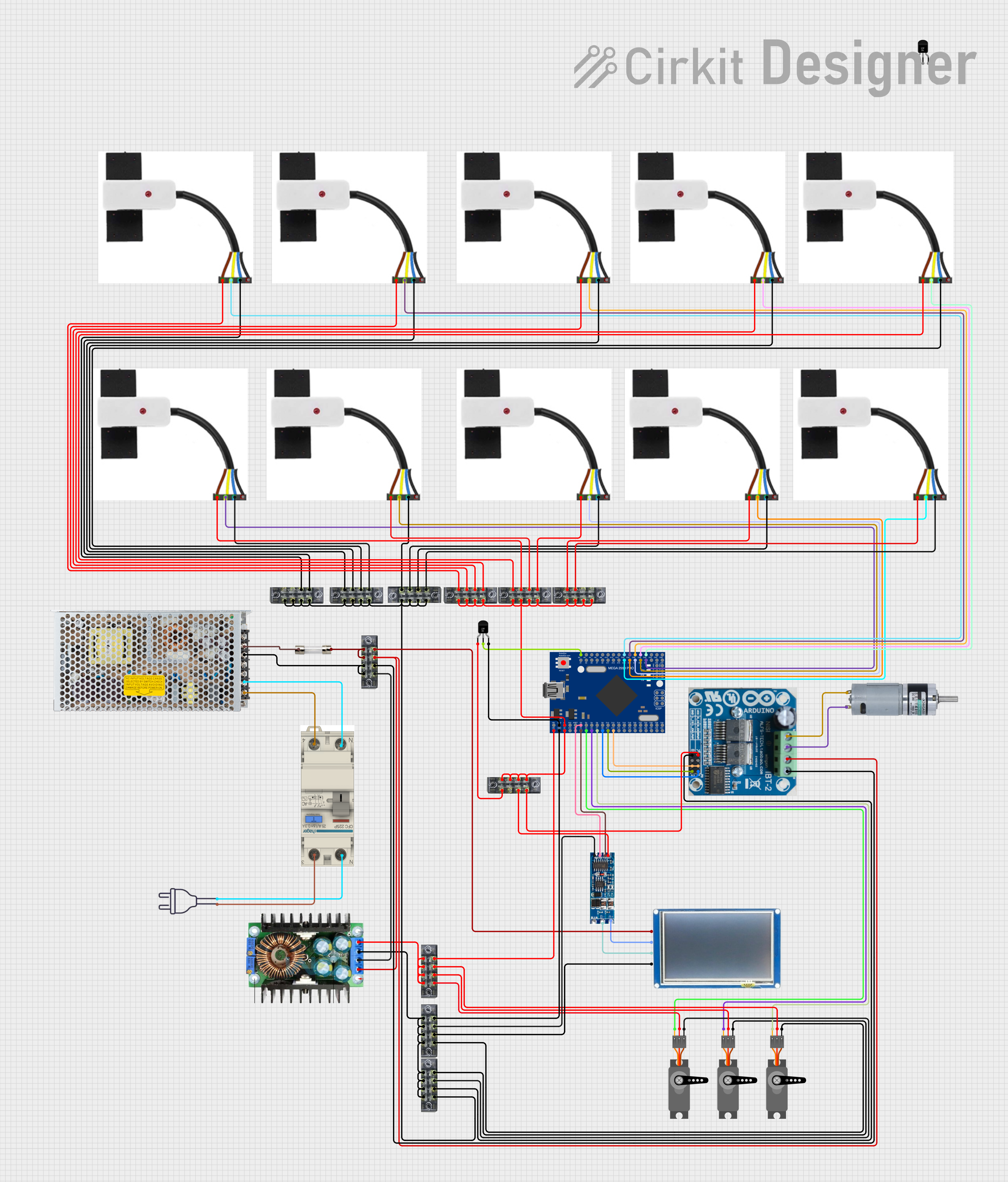
Mega2560-Controlled Automation System with Non-Contact Liquid Level Sensing and Motor Control
Image of Project_AutomaticBartender: A project utilizing XYS3580 in a practical application
This circuit appears to be a complex control system centered around an Arduino Mega2560 R3 Pro microcontroller, which interfaces with multiple sensors (XKC-Y26-V non-contact liquid level sensors and an LM35 temperature sensor), servo motors, a touch display, and an IBT-2 H-Bridge motor driver for controlling a planetary gearbox motor. The system also includes a UART TTL to RS485 converter for communication, likely with the touch display, and a power management subsystem with a switching power supply, fuses, and circuit breakers for safety and voltage regulation (XL4016). The absence of embedded code suggests that the functionality of the microcontroller is not defined within the provided data.
Cirkit Designer LogoOpen Project in Cirkit Designer
Cellular-Enabled IoT Device with Real-Time Clock and Power Management
Image of LRCM PHASE 2 BASIC: A project utilizing XYS3580 in a practical application
This circuit features a LilyGo-SIM7000G module for cellular communication and GPS functionality, interfaced with an RTC DS3231 for real-time clock capabilities. It includes voltage sensing through two voltage sensor modules, and uses an 8-channel opto-coupler for isolating different parts of the circuit. Power management is handled by a buck converter connected to a DC power source and batteries, with a fuse for protection and a rocker switch for on/off control. Additionally, there's an LED for indication purposes.
Cirkit Designer LogoOpen Project in Cirkit Designer
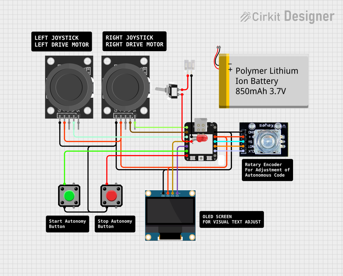
Battery-Powered ESP32-C3 Interactive Control Panel
Image of GTV-Transmitter Advanced: A project utilizing XYS3580 in a practical application
This circuit features an ESP32-C3 microcontroller connected to various input devices and an OLED display. The input devices include two KY-023 Dual Axis Joystick Modules for directional input and a Rotary Encoder for incremental input, both interfaced with the ESP32-C3's GPIO pins. The circuit also includes a power management system with a Polymer Lithium Ion Battery, a JST connector, and a toggle switch to control power to an LED indicator.
Cirkit Designer LogoOpen Project in Cirkit Designer

Explore Projects Built with XYS3580

Use Cirkit Designer to design, explore, and prototype these projects online. Some projects support real-time simulation. Click "Open Project" to start designing instantly!
Image of GPS 시스템 측정 구성도_Confirm: A project utilizing XYS3580 in a practical application
Satellite-Based Timing and Navigation System with SDR and Atomic Clock Synchronization
This circuit appears to be a complex system involving power supply management, GPS and timing synchronization, and data communication. It includes a SI-TEX G1 Satellite Compass for GPS data, an XHTF1021 Atomic Rubidium Clock for precise timing, and Ettus USRP B200 units for software-defined radio communication. Power is supplied through various SMPS units and distributed via terminal blocks and DC jacks. Data communication is facilitated by Beelink MINI S12 N95 computers, RS232 splitters, and a 1000BASE-T Media Converter for network connectivity. RF Directional Couplers are used to interface antennas with the USRP units, and the entire system is likely contained within cases for protection and organization.
Cirkit Designer LogoOpen Project in Cirkit Designer
Image of Project_AutomaticBartender: A project utilizing XYS3580 in a practical application
Mega2560-Controlled Automation System with Non-Contact Liquid Level Sensing and Motor Control
This circuit appears to be a complex control system centered around an Arduino Mega2560 R3 Pro microcontroller, which interfaces with multiple sensors (XKC-Y26-V non-contact liquid level sensors and an LM35 temperature sensor), servo motors, a touch display, and an IBT-2 H-Bridge motor driver for controlling a planetary gearbox motor. The system also includes a UART TTL to RS485 converter for communication, likely with the touch display, and a power management subsystem with a switching power supply, fuses, and circuit breakers for safety and voltage regulation (XL4016). The absence of embedded code suggests that the functionality of the microcontroller is not defined within the provided data.
Cirkit Designer LogoOpen Project in Cirkit Designer
Image of LRCM PHASE 2 BASIC: A project utilizing XYS3580 in a practical application
Cellular-Enabled IoT Device with Real-Time Clock and Power Management
This circuit features a LilyGo-SIM7000G module for cellular communication and GPS functionality, interfaced with an RTC DS3231 for real-time clock capabilities. It includes voltage sensing through two voltage sensor modules, and uses an 8-channel opto-coupler for isolating different parts of the circuit. Power management is handled by a buck converter connected to a DC power source and batteries, with a fuse for protection and a rocker switch for on/off control. Additionally, there's an LED for indication purposes.
Cirkit Designer LogoOpen Project in Cirkit Designer
Image of GTV-Transmitter Advanced: A project utilizing XYS3580 in a practical application
Battery-Powered ESP32-C3 Interactive Control Panel
This circuit features an ESP32-C3 microcontroller connected to various input devices and an OLED display. The input devices include two KY-023 Dual Axis Joystick Modules for directional input and a Rotary Encoder for incremental input, both interfaced with the ESP32-C3's GPIO pins. The circuit also includes a power management system with a Polymer Lithium Ion Battery, a JST connector, and a toggle switch to control power to an LED indicator.
Cirkit Designer LogoOpen Project in Cirkit Designer

Common Applications and Use Cases

  • RF mixers and detectors
  • Power rectifiers in power supplies
  • Voltage clamping and protection circuits
  • High-frequency switch-mode power supplies

Technical Specifications

Key Technical Details

  • Forward Current (If): Specified in Amperes (A)
  • Peak Reverse Voltage (Vr): Specified in Volts (V)
  • Forward Voltage Drop (Vf): Specified at a given forward current, in Volts (V)
  • Reverse Leakage Current (Ir): Specified at a given reverse voltage, in Microamperes (µA)
  • Junction Capacitance (Cj): Specified at a given reverse voltage, in Picofarads (pF)
  • Switching Speed: Specified in Nanoseconds (ns)

Pin Configuration and Descriptions

Pin Number Description Notes
1 Anode Connects to the positive supply
2 Cathode Connects to the negative supply

Usage Instructions

How to Use the Component in a Circuit

  1. Forward Biasing: To use the XYS3580 in a forward-biased configuration, connect the anode to a positive voltage and the cathode to a negative voltage or ground.

  2. Reverse Biasing: For reverse biasing, reverse the connections. Note that exceeding the peak reverse voltage can damage the diode.

  3. RF Applications: In RF circuits, the diode can be used in mixers or detectors. Ensure proper impedance matching for optimal performance.

Important Considerations and Best Practices

  • Heat Management: The XYS3580 can handle high power, but it is crucial to manage heat dissipation to prevent thermal runaway. Use appropriate heat sinking.
  • Reverse Voltage Protection: Always ensure that the reverse voltage does not exceed the specified peak reverse voltage.
  • Soldering: Avoid excessive heat and prolonged soldering times to prevent damage to the diode.
  • Static Discharge: As with all semiconductor devices, take precautions against electrostatic discharge (ESD) during handling and installation.

Troubleshooting and FAQs

Common Issues Users Might Face

  • Excessive Heat: If the diode is running hot, check the current flow and ensure it is within the specified forward current rating. Also, improve heat sinking.
  • Diode Not Conducting: Ensure that the diode is correctly biased and that the forward voltage is above the threshold.
  • Unexpected Voltage Drops: Check for correct orientation and that the diode is not damaged or reverse-biased.

Solutions and Tips for Troubleshooting

  • Heat Issues: Attach the diode to a larger heat sink or improve airflow around the component.
  • Conduction Issues: Verify the orientation and ensure the diode is forward-biased with the correct polarity.
  • Voltage Issues: If the diode has an unexpected voltage drop, test it with a multimeter to ensure it is functioning correctly.

FAQs

Q: Can the XYS3580 be used for DC applications? A: Yes, it can rectify high-frequency AC signals to DC, but it is optimized for RF applications.

Q: What is the maximum frequency the XYS3580 can handle? A: The maximum frequency depends on the specific model and should be checked in the datasheet. Generally, Schottky diodes are suitable for high-frequency applications.

Q: How do I protect the diode from ESD? A: Use ESD protection such as wrist straps and ESD mats when handling the diode, and store it in anti-static packaging.

Note: The XYS3580 is not typically used with an Arduino UNO or similar microcontroller platforms, as it is designed for high-power RF applications. Therefore, example code for Arduino is not applicable for this component.