How to Use 74HC14: Examples, Pinouts, and Specs

Introduction
The 74HC14 is an integrated circuit that consists of six independent inverters with Schmitt trigger inputs. This component is widely used in digital electronics for signal conditioning, by converting noisy or slow input signals into sharply defined, jitter-free output signals. The Schmitt trigger feature adds hysteresis to the input, allowing the device to ignore small fluctuations and noise, which is particularly useful in applications where signals are prone to interference.
Explore Projects Built with 74HC14

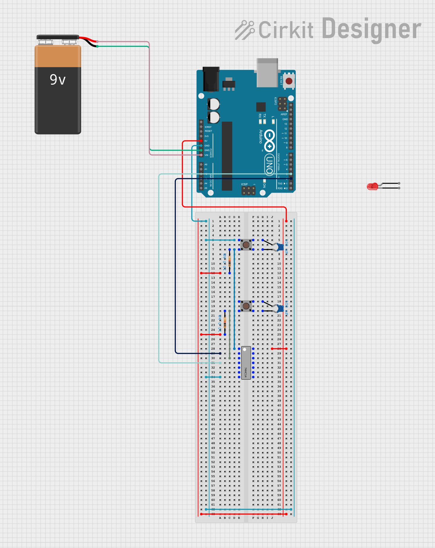

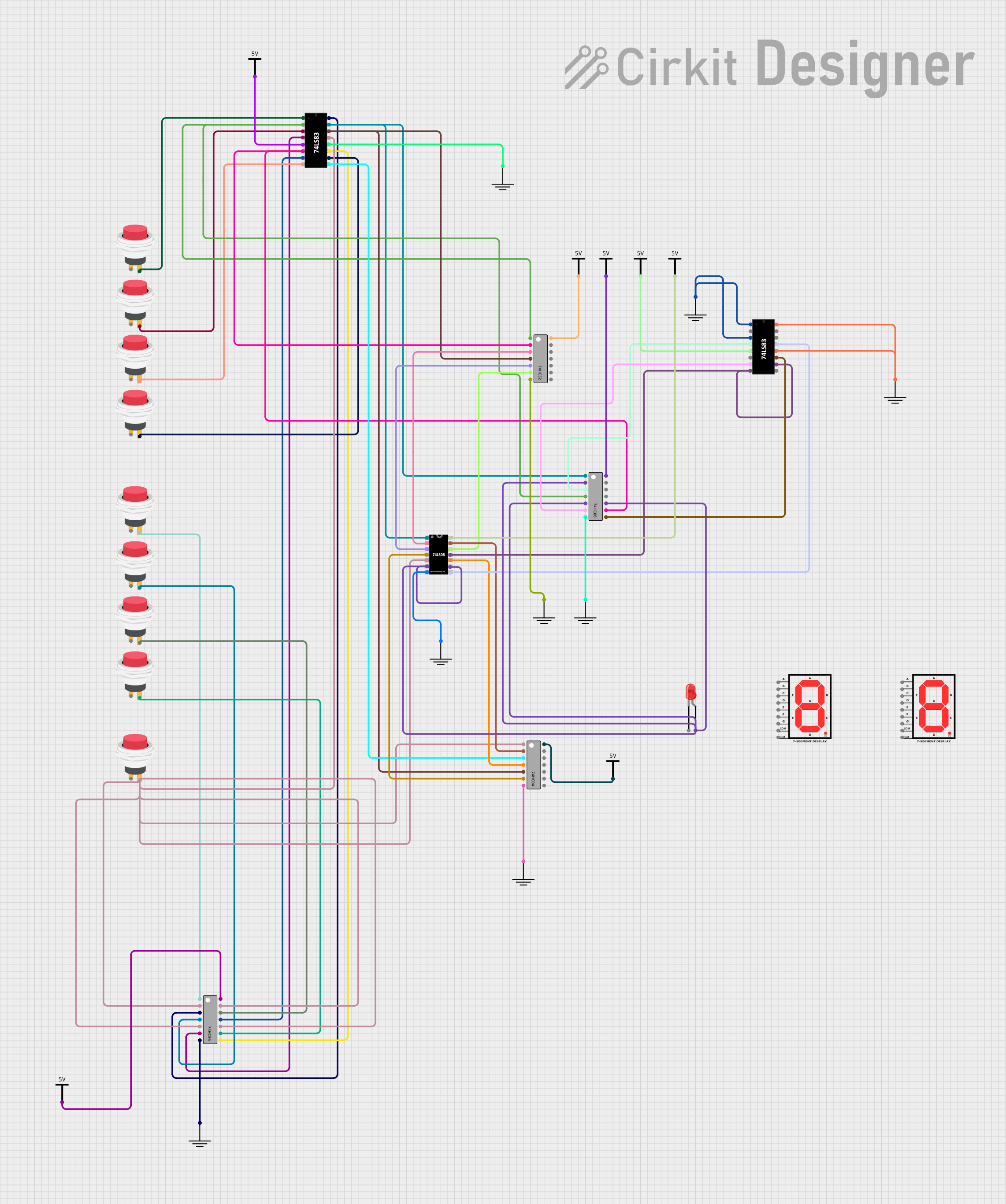
Explore Projects Built with 74HC14
Common Applications and Use Cases
- Signal conditioning
- Waveform shaping
- Oscillator circuits
- Logic level conversion
- Debouncing switches and buttons
Technical Specifications
Key Technical Details
- Supply Voltage (Vcc): 2.0V to 6.0V
- Input Voltage (Vin): -0.5V to Vcc + 0.5V
- Output Voltage (Vout): -0.5V to Vcc + 0.5V
- High-Level Input Voltage (VIH): Minimum 2V (for Vcc = 6V)
- Low-Level Input Voltage (VIL): Maximum 0.8V (for Vcc = 6V)
- Propagation Delay Time: Approx. 13 ns (for Vcc = 6V)
- Hysteresis Voltage (Typical): 0.9V (for Vcc = 4.5V)
Pin Configuration and Descriptions
| Pin Number | Name | Description |
|---|---|---|
| 1 | 1A | Input of inverter 1 |
| 2 | 1Y | Output of inverter 1 |
| 3 | 2A | Input of inverter 2 |
| 4 | 2Y | Output of inverter 2 |
| 5 | 3A | Input of inverter 3 |
| 6 | 3Y | Output of inverter 3 |
| 7 | GND | Ground (0V) |
| 8 | 4Y | Output of inverter 4 |
| 9 | 4A | Input of inverter 4 |
| 10 | 5Y | Output of inverter 5 |
| 11 | 5A | Input of inverter 5 |
| 12 | 6Y | Output of inverter 6 |
| 13 | 6A | Input of inverter 6 |
| 14 | Vcc | Positive supply voltage |
Usage Instructions
How to Use the 74HC14 in a Circuit
Power Supply Connection: Connect pin 14 (Vcc) to the positive supply voltage within the range of 2.0V to 6.0V. Connect pin 7 (GND) to the ground of the circuit.
Input Connection: Apply the input signal to the input pin (A) of the desired inverter.
Output Connection: The output pin (Y) provides the inverted signal. Connect this to the subsequent stage of your circuit.
Decoupling Capacitor: It is good practice to place a 0.1 µF ceramic decoupling capacitor close to the Vcc pin to filter out noise.
Important Considerations and Best Practices
- Ensure that the input voltage does not exceed the specified limits to prevent damage.
- Unused inputs should be tied to Vcc or GND to avoid floating inputs, which can cause erratic behavior.
- The total current drawn from all outputs must not exceed the maximum specified current rating for the device.
Example Circuit: Debouncing a Pushbutton
// Arduino code to debounce a pushbutton using 74HC14
const int buttonPin = 2; // Connect the debounced output to digital pin 2
const int ledPin = 13;   // LED connected to digital pin 13

void setup() {
  pinMode(ledPin, OUTPUT);      // Set the LED pin as output
  pinMode(buttonPin, INPUT);    // Set the button pin as input
}

void loop() {
  int buttonState = digitalRead(buttonPin); // Read the button state
  digitalWrite(ledPin, buttonState);        // Set the LED to the button state
}
In this example, the pushbutton is connected to the input of one of the 74HC14 inverters, and the output is connected to the Arduino digital pin 2. The 74HC14 cleans up the signal from the pushbutton, providing a stable HIGH or LOW signal to the Arduino.
Troubleshooting and FAQs
Common Issues Users Might Face
- Signal not inverting: Check if the input is within the valid range and if the Vcc and GND are properly connected.
- Output remains constant: Ensure that the input is not floating and is connected to a valid logic level.
- Device heating up: This could be due to supply voltage exceeding the maximum rating or excessive output current. Verify the supply voltage and current draw.
Solutions and Tips for Troubleshooting
- Always double-check the pin connections and ensure that the power supply is within the recommended range.
- If the output is not as expected, measure the input and output voltages with an oscilloscope to verify the signal levels and hysteresis behavior.
- For noise issues, consider adding a bypass capacitor between Vcc and GND.
FAQs
Q: Can I use the 74HC14 for analog signals? A: No, the 74HC14 is designed for digital signals and will not work properly with analog signals.
Q: What is the purpose of the Schmitt trigger in the 74HC14? A: The Schmitt trigger adds hysteresis to the input, which helps to stabilize signals that are noisy or have slow rising/falling edges, resulting in a cleaner digital output.
Q: How do I handle unused inputs on the 74HC14? A: Unused inputs should be tied to either Vcc or GND to prevent them from floating, which can cause unpredictable behavior.
Q: Can the 74HC14 be used to generate an oscillating signal? A: Yes, by creating a feedback loop with a resistor and capacitor, the 74HC14 can be configured as an oscillator.
This documentation provides a comprehensive guide to using the 74HC14 hex inverter with Schmitt trigger inputs. For further information, consult the manufacturer's datasheet.