How to Use Arduino UNO/input node: Examples, Pinouts, and Specs
Introduction
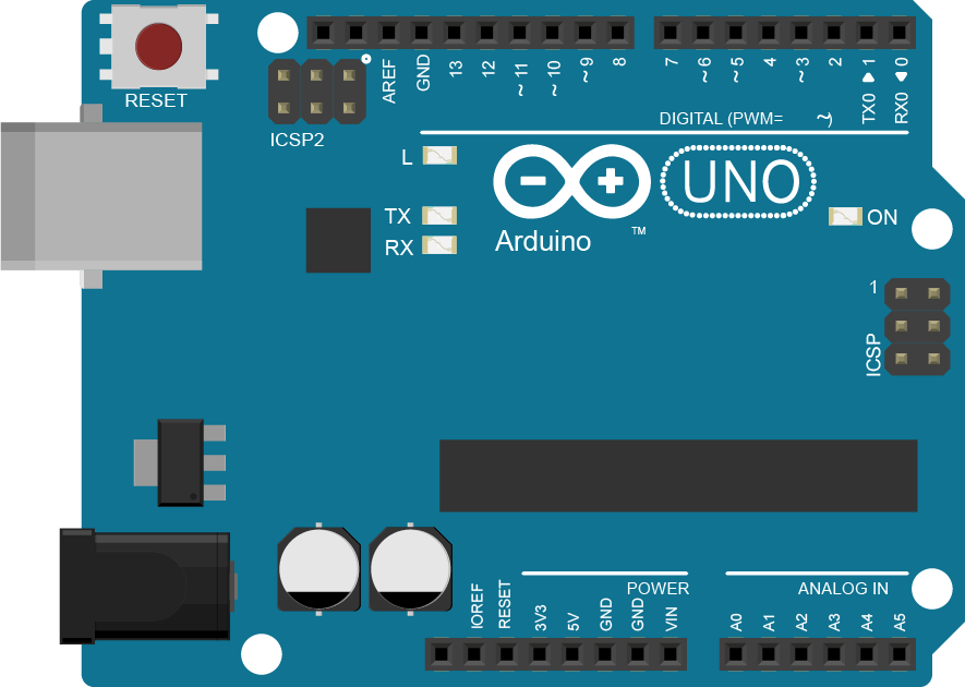
The Arduino UNO is a widely used microcontroller board based on the ATmega328P. It is designed for beginners and professionals to create interactive electronic projects. An input node refers to any pin or interface on the Arduino UNO that is configured to receive data or signals from external components, such as sensors, buttons, or other devices.
Input nodes are essential for gathering data from the environment or user interactions, enabling the Arduino to make decisions or trigger actions based on the received input. These nodes are commonly used in projects like temperature monitoring, motion detection, and user-controlled devices.
Explore Projects Built with Arduino UNO/input node
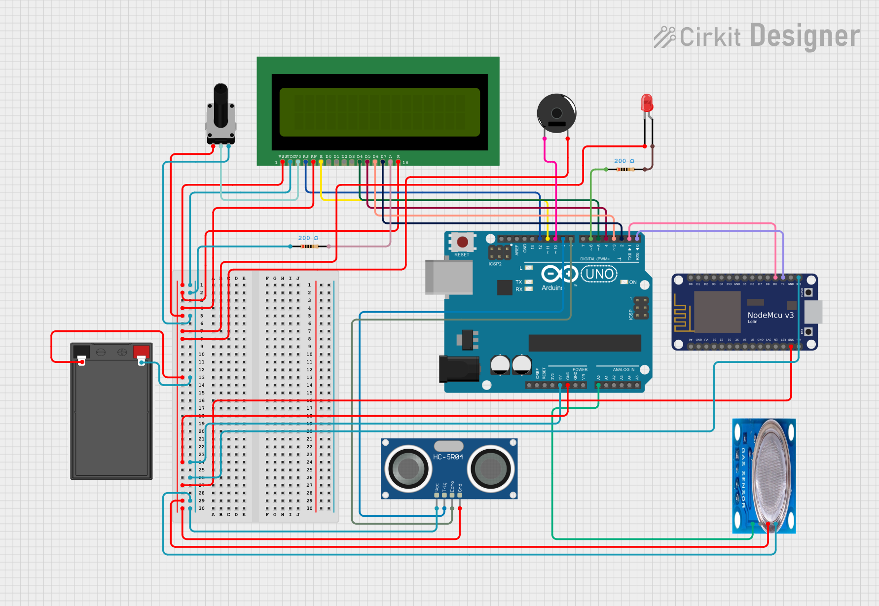
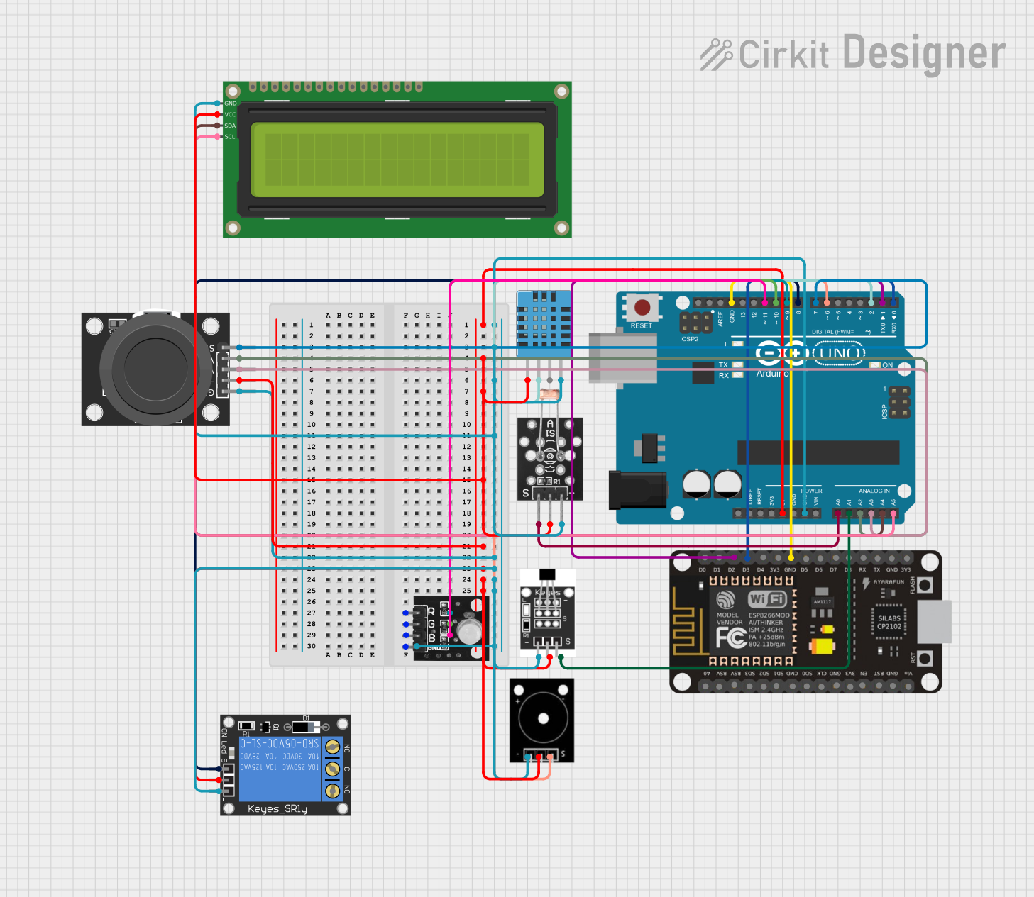
Explore Projects Built with Arduino UNO/input node
Technical Specifications
The Arduino UNO has 14 digital input/output pins (of which 6 can be used as PWM outputs) and 6 analog input pins. Below are the key specifications for input nodes:
General Specifications
- Operating Voltage: 5V
- Input Voltage (recommended): 7-12V
- Digital Input Voltage Levels:
- LOW: 0V to 1.5V
- HIGH: 3V to 5V
- Analog Input Voltage Range: 0V to 5V
- Analog Resolution: 10-bit (values range from 0 to 1023)
- Maximum Current per Pin: 40mA
Pin Configuration and Descriptions
Digital Pins
| Pin Number | Functionality | Description |
|---|---|---|
| D0-D13 | Digital Input/Output | Can be configured as input or output. |
| D2-D13 | Interrupt Capable (D2, D3) | Supports external interrupts. |
| D3, D5, D6, D9, D10, D11 | PWM Capable | Can output PWM signals. |
Analog Pins
| Pin Number | Functionality | Description |
|---|---|---|
| A0-A5 | Analog Input | Reads analog signals (0-5V). |
| A4, A5 | I2C Communication (SDA, SCL) | Can be used for I2C communication. |
Usage Instructions
Configuring a Digital Input Node
To use a digital pin as an input node, configure it in the setup() function using the pinMode() function. For example, a button can be connected to a digital pin to detect user input.
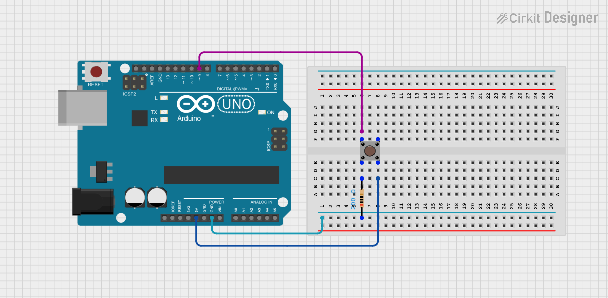
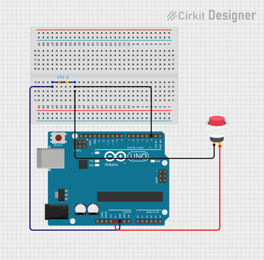
Example Circuit
- Connect one terminal of the button to digital pin 2.
- Connect the other terminal of the button to GND.
- Use a pull-up resistor (10kΩ) between the button and 5V to ensure a stable signal.
Example Code
// Define the pin connected to the button
const int buttonPin = 2;

// Variable to store the button state
int buttonState = 0;

void setup() {
  // Configure the button pin as an input
  pinMode(buttonPin, INPUT);

  // Start the serial communication for debugging
  Serial.begin(9600);
}

void loop() {
  // Read the state of the button
  buttonState = digitalRead(buttonPin);

  // Print the button state to the Serial Monitor
  Serial.print("Button State: ");
  Serial.println(buttonState);

  // Add a small delay to avoid spamming the Serial Monitor
  delay(100);
}
Configuring an Analog Input Node
Analog input nodes are used to read varying voltage levels, such as those from a potentiometer or a temperature sensor.
Example Circuit
- Connect the middle pin of a potentiometer to analog pin A0.
- Connect one outer pin of the potentiometer to 5V and the other to GND.
Example Code
// Define the pin connected to the potentiometer
const int potPin = A0;

// Variable to store the potentiometer value
int potValue = 0;

void setup() {
  // Start the serial communication for debugging
  Serial.begin(9600);
}

void loop() {
  // Read the analog value from the potentiometer
  potValue = analogRead(potPin);

  // Print the potentiometer value to the Serial Monitor
  Serial.print("Potentiometer Value: ");
  Serial.println(potValue);

  // Add a small delay to stabilize readings
  delay(100);
}
Important Considerations
- Voltage Levels: Ensure that the input voltage does not exceed 5V to avoid damaging the Arduino.
- Pull-up/Pull-down Resistors: Use pull-up or pull-down resistors for stable digital input signals.
- Debouncing: For mechanical switches or buttons, implement debouncing in software or hardware to avoid false triggers.
- Analog Signal Conditioning: Use appropriate signal conditioning (e.g., filters) for noisy analog inputs.
Troubleshooting and FAQs
Common Issues
Input Not Detected:
- Cause: Incorrect pin configuration.
- Solution: Verify that the pin is configured as an input using
pinMode().
Unstable Readings:
- Cause: No pull-up or pull-down resistor for digital inputs.
- Solution: Add a pull-up or pull-down resistor to stabilize the signal.
Analog Values Out of Range:
- Cause: Input voltage exceeds 5V.
- Solution: Ensure the input voltage is within the 0-5V range.
Button Press Not Registered:
- Cause: Debouncing issue.
- Solution: Implement a software debounce routine or use a capacitor for hardware debouncing.
FAQs
Can I use digital pins as analog inputs?
- No, digital pins cannot read analog signals. Use the analog pins (A0-A5) for this purpose.
What happens if I exceed the maximum input voltage?
- Exceeding 5V can permanently damage the Arduino UNO. Use voltage dividers or level shifters for higher voltages.
How do I read multiple inputs simultaneously?
- Use separate pins for each input and read them sequentially in the
loop()function.
- Use separate pins for each input and read them sequentially in the
By following this documentation, you can effectively use the Arduino UNO's input nodes for a wide range of applications.