Cirkit Designer
Your all-in-one circuit design IDE
Home /
Component Documentation
How to Use gps_circuit_image: Examples, Pinouts, and Specs
Introduction
- A GPS Circuit Image is a visual representation of the arrangement and connections of components used in GPS technology. It provides a clear understanding of how various electronic components, such as GPS modules, microcontrollers, and power supplies, are interconnected to enable location tracking and navigation.
- Common applications include:
- Vehicle tracking systems
- Handheld GPS devices
- IoT-based location tracking solutions
- Navigation systems in drones and robotics
Explore Projects Built with gps_circuit_image
ESP32-Based GPS Tracker with OLED Display and Firebase Integration

This circuit is a GPS tracking system that uses an ESP32 microcontroller to read location data from a NEO-6M GPS module and display information on a 0.96" OLED screen. The system is powered by a 2000mAh battery with a lithium-ion charger, and it uploads the GPS data to Firebase via WiFi. Additional components include an MPU6050 accelerometer/gyroscope for motion sensing and a buzzer for alerts.
ESP32-Based GPS Tracker with OLED Display and Telegram Integration

This circuit is a GPS-based tracking system that uses an ESP32 microcontroller to receive GPS data from a NEO 6M module and display the coordinates on a 1.3" OLED screen. It also features WiFi connectivity to send location updates to a remote server, potentially for applications such as asset tracking or navigation assistance.
Raspberry Pi Pico-Based Navigation System with Bluetooth and GPS
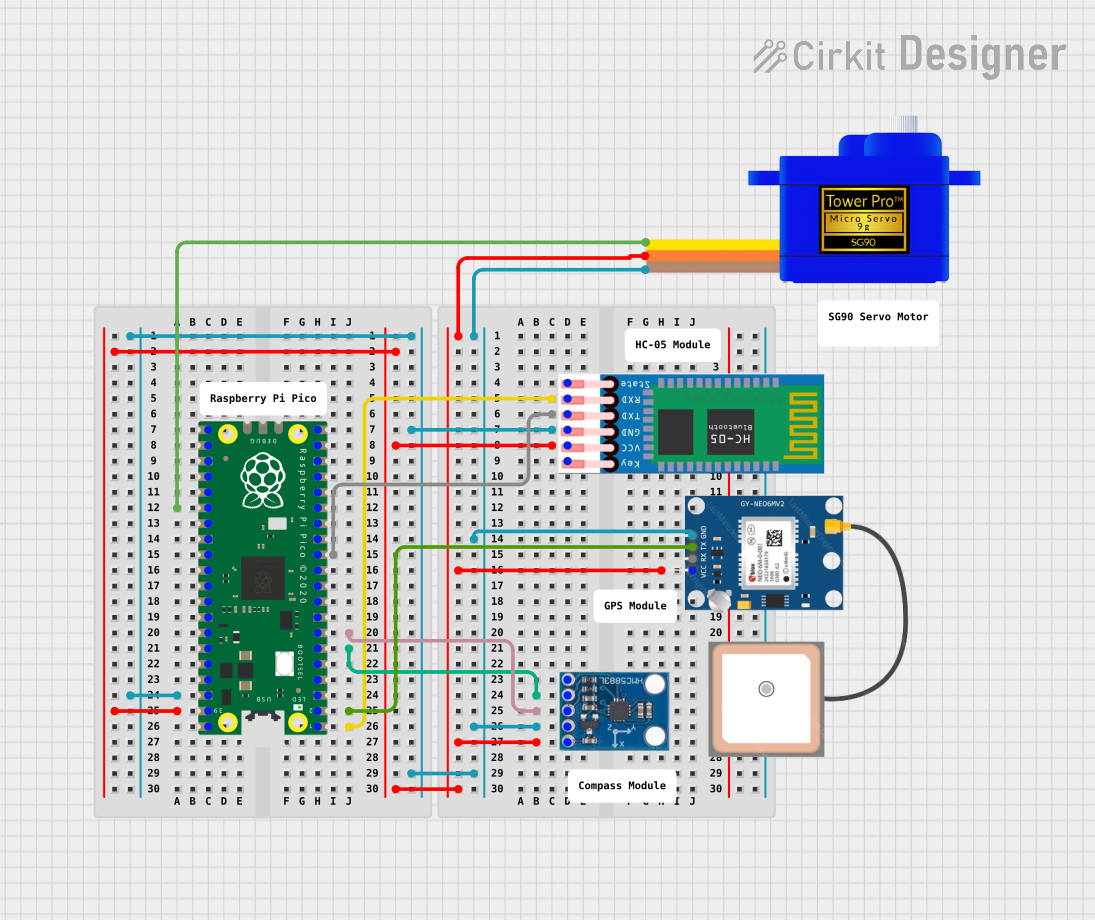
This circuit features a Raspberry Pi Pico microcontroller interfaced with multiple peripherals for navigation and control. It includes an HC-05 Bluetooth module for wireless communication, an HMC5883L compass for magnetic heading detection, a GPS NEO 6M module for location tracking, and an SG90 servomotor for actuation. The Pico manages data exchange with the GPS and compass via serial connections, controls the servomotor, and communicates wirelessly through the HC-05 module.
ESP32-Based Health and Location Tracker with GPS and Heart Rate Monitoring
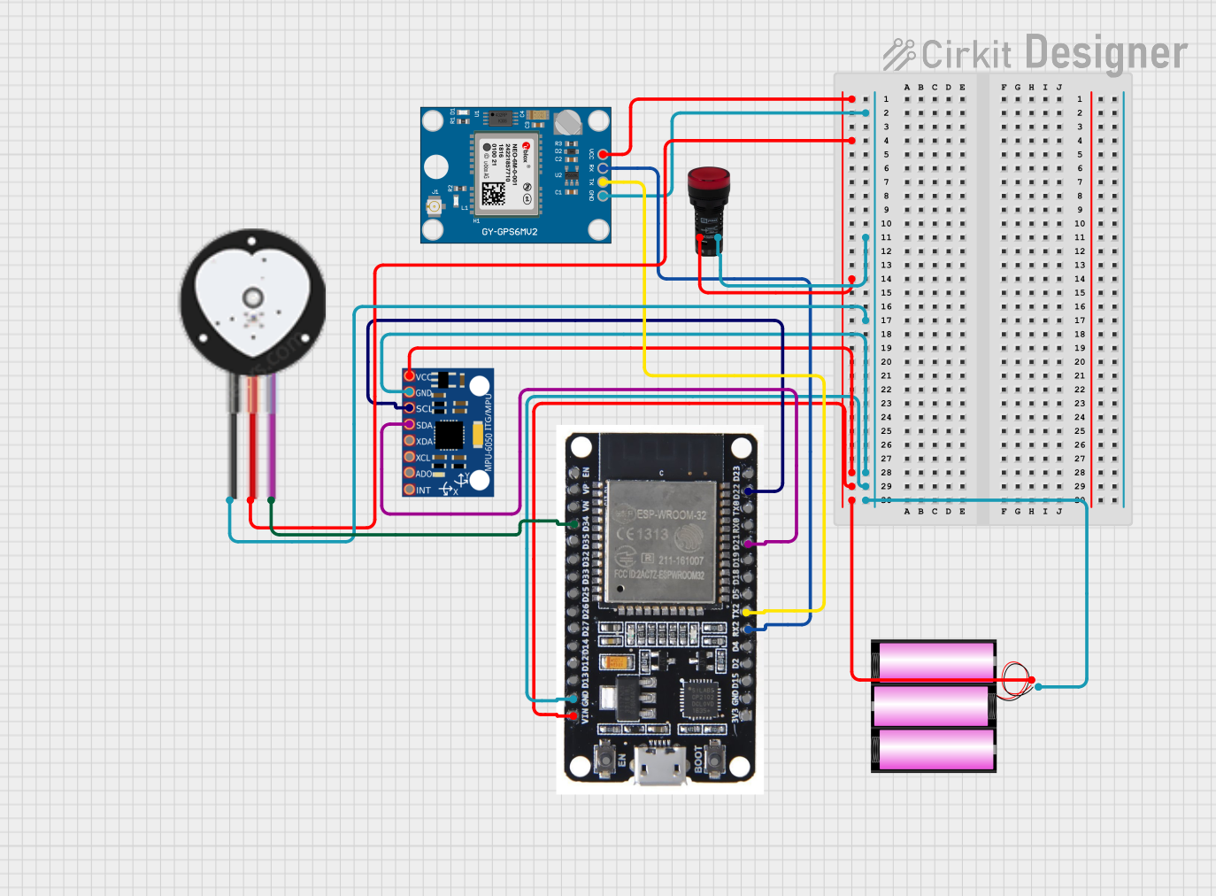
This circuit features an ESP32 microcontroller connected to an MPU-6050 motion sensor, a heart pulse sensor, and a Neo 6M GPS module, designed for tracking motion, heart rate, and GPS location. A pilot lamp indicates operational status, and a 12V battery powers the entire system.
Explore Projects Built with gps_circuit_image
ESP32-Based GPS Tracker with OLED Display and Firebase Integration
This circuit is a GPS tracking system that uses an ESP32 microcontroller to read location data from a NEO-6M GPS module and display information on a 0.96" OLED screen. The system is powered by a 2000mAh battery with a lithium-ion charger, and it uploads the GPS data to Firebase via WiFi. Additional components include an MPU6050 accelerometer/gyroscope for motion sensing and a buzzer for alerts.
ESP32-Based GPS Tracker with OLED Display and Telegram Integration
This circuit is a GPS-based tracking system that uses an ESP32 microcontroller to receive GPS data from a NEO 6M module and display the coordinates on a 1.3" OLED screen. It also features WiFi connectivity to send location updates to a remote server, potentially for applications such as asset tracking or navigation assistance.
Raspberry Pi Pico-Based Navigation System with Bluetooth and GPS
This circuit features a Raspberry Pi Pico microcontroller interfaced with multiple peripherals for navigation and control. It includes an HC-05 Bluetooth module for wireless communication, an HMC5883L compass for magnetic heading detection, a GPS NEO 6M module for location tracking, and an SG90 servomotor for actuation. The Pico manages data exchange with the GPS and compass via serial connections, controls the servomotor, and communicates wirelessly through the HC-05 module.
ESP32-Based Health and Location Tracker with GPS and Heart Rate Monitoring
This circuit features an ESP32 microcontroller connected to an MPU-6050 motion sensor, a heart pulse sensor, and a Neo 6M GPS module, designed for tracking motion, heart rate, and GPS location. A pilot lamp indicates operational status, and a 12V battery powers the entire system.
Technical Specifications
While the GPS Circuit Image itself is not an electronic component, it typically represents the following key components and their specifications:
Key Components Represented in a GPS Circuit
| Component Name | Description |
|---|---|
| GPS Module | Receives satellite signals and calculates location coordinates. |
| Microcontroller | Processes GPS data and communicates with other devices (e.g., Arduino). |
| Power Supply | Provides the required voltage and current to the circuit (e.g., 3.3V or 5V). |
| Antenna | Captures GPS signals from satellites. |
| Communication Ports | Interfaces like UART, I2C, or SPI for data transfer. |
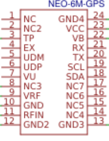
Example Pin Configuration for a GPS Module
| Pin Name | Pin Number | Description |
|---|---|---|
| VCC | 1 | Power input (typically 3.3V or 5V). |
| GND | 2 | Ground connection. |
| TX | 3 | Transmit pin for sending GPS data to the microcontroller. |
| RX | 4 | Receive pin for receiving data from the microcontroller (if applicable). |
| PPS | 5 | Pulse-per-second output for precise timing (optional). |
Usage Instructions
To use a GPS circuit as represented in the image, follow these steps:
Connect the GPS Module:
- Connect the VCC pin of the GPS module to a 3.3V or 5V power source, depending on the module's requirements.
- Connect the GND pin to the ground of the circuit.
- Connect the TX pin of the GPS module to the RX pin of the microcontroller (e.g., Arduino UNO).
- Optionally, connect the RX pin of the GPS module to the TX pin of the microcontroller for two-way communication.
Integrate with a Microcontroller:
- Use a microcontroller like an Arduino UNO to process the GPS data.
- Install the necessary libraries (e.g., TinyGPS++ for Arduino) to decode GPS data.
Write and Upload Code:
- Below is an example Arduino code snippet to read GPS data:
#include <SoftwareSerial.h>
#include <TinyGPS++.h>

// Create a SoftwareSerial instance for GPS communication
SoftwareSerial gpsSerial(4, 3); // RX, TX pins for GPS module
TinyGPSPlus gps; // Create a TinyGPS++ object

void setup() {
  Serial.begin(9600); // Initialize Serial Monitor
  gpsSerial.begin(9600); // Initialize GPS module communication
  Serial.println("GPS Module Test");
}

void loop() {
  // Check if data is available from the GPS module
  while (gpsSerial.available() > 0) {
    if (gps.encode(gpsSerial.read())) { // Decode GPS data
      if (gps.location.isUpdated()) { // Check if location data is updated
        Serial.print("Latitude: ");
        Serial.println(gps.location.lat(), 6); // Print latitude
        Serial.print("Longitude: ");
        Serial.println(gps.location.lng(), 6); // Print longitude
      }
    }
  }
}
Power the Circuit:
- Ensure the power supply matches the voltage and current requirements of the GPS module and other components.
Test the Circuit:
- Open the Serial Monitor in the Arduino IDE to view the GPS data, such as latitude and longitude.
Important Considerations
- Use a GPS module with an external antenna for better signal reception, especially indoors.
- Ensure the microcontroller's UART pins are compatible with the GPS module's voltage levels.
- Place the GPS antenna in an open area for optimal satellite signal reception.
Troubleshooting and FAQs
Common Issues
No GPS Data Received:
- Cause: Poor satellite signal reception.
- Solution: Move the GPS antenna to an open area with a clear view of the sky.
Incorrect or No Location Data:
- Cause: Incorrect wiring or baud rate mismatch.
- Solution: Double-check the connections and ensure the baud rate in the code matches the GPS module's default baud rate.
Microcontroller Not Communicating with GPS Module:
- Cause: Voltage level mismatch or incorrect pin connections.
- Solution: Use a level shifter if the GPS module operates at 3.3V and the microcontroller at 5V. Verify the TX and RX connections.
FAQs
Can I use the GPS circuit indoors?
- GPS signals are weaker indoors. Use an external antenna or consider GPS modules with better sensitivity.
What is the typical accuracy of a GPS module?
- Most GPS modules provide an accuracy of 2.5 meters under ideal conditions.
Can I use this circuit with a Raspberry Pi?
- Yes, connect the GPS module to the Raspberry Pi's UART pins and use libraries like
gpsdfor data processing.
- Yes, connect the GPS module to the Raspberry Pi's UART pins and use libraries like
By following this documentation, you can effectively understand and utilize a GPS circuit as represented in the image for location tracking and navigation applications.