How to Use charger module circuit : Examples, Pinouts, and Specs
Introduction
The ETA9650 is a highly efficient charger module circuit designed to convert AC or DC power into a suitable voltage and current for charging batteries or powering devices. Manufactured by ETA, this module integrates advanced features to ensure safe, reliable, and efficient charging. It is commonly used in portable electronics, power banks, IoT devices, and other battery-powered applications.
Explore Projects Built with charger module circuit


Explore Projects Built with charger module circuit
Common Applications
- Charging lithium-ion or lithium-polymer batteries
- Powering portable electronic devices
- Integration into power banks and battery management systems
- IoT devices requiring compact and efficient charging solutions
Technical Specifications
The ETA9650 charger module circuit is designed with robust technical capabilities to meet the demands of modern electronic devices. Below are the key specifications:
Key Technical Details
| Parameter | Value |
|---|---|
| Input Voltage Range | 4.5V to 28V |
| Output Voltage | Configurable (up to 4.2V) |
| Maximum Output Current | 2A |
| Charging Algorithm | CC (Constant Current) / CV (Constant Voltage) |
| Efficiency | Up to 95% |
| Operating Temperature | -40°C to +85°C |
| Package Type | DFN-10 (3mm x 3mm) |
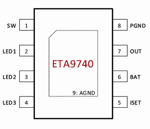
Pin Configuration and Descriptions
The ETA9650 module features a 10-pin DFN package. Below is the pinout and description:
| Pin Number | Pin Name | Description |
|---|---|---|
| 1 | VIN | Input voltage pin (4.5V to 28V) |
| 2 | GND | Ground pin |
| 3 | BAT | Battery connection pin |
| 4 | CHG_OK | Charging status indicator (active low) |
| 5 | ISET | Current setting pin (sets charging current) |
| 6 | EN | Enable pin (active high to enable charging) |
| 7 | NTC | Temperature monitoring pin for battery safety |
| 8 | STAT | Status pin (indicates charging state) |
| 9 | VREF | Reference voltage output |
| 10 | NC | No connection |
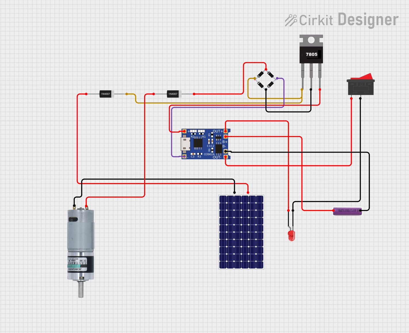
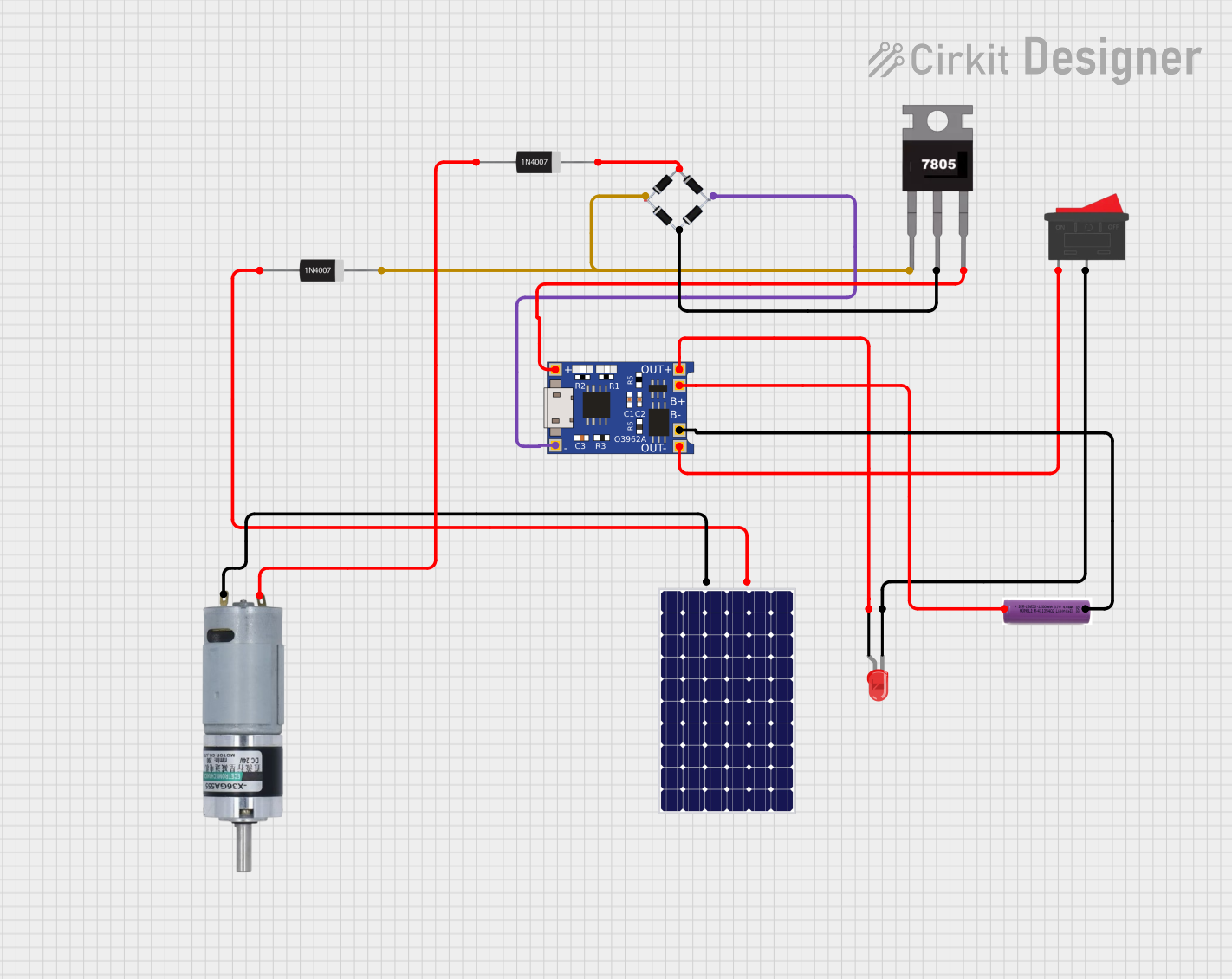
Usage Instructions
The ETA9650 charger module circuit is straightforward to use in a variety of applications. Below are the steps and considerations for integrating it into your design:
How to Use the ETA9650 in a Circuit
- Power Supply: Connect a DC power source (4.5V to 28V) to the
VINpin. Ensure the input voltage is within the specified range. - Battery Connection: Connect the positive terminal of the battery to the
BATpin and the negative terminal toGND. - Set Charging Current: Use a resistor on the
ISETpin to configure the desired charging current. Refer to the datasheet for the resistor value corresponding to your required current. - Enable Charging: Pull the
ENpin high to enable charging. If left floating, the module will remain disabled. - Monitor Status: Use the
CHG_OKandSTATpins to monitor the charging status. These pins can be connected to LEDs or a microcontroller for visual or digital feedback. - Temperature Monitoring: Connect an NTC thermistor to the
NTCpin for battery temperature monitoring. This ensures safe charging by halting the process if the battery temperature exceeds safe limits.
Important Considerations
- Thermal Management: Ensure proper heat dissipation, especially when charging at high currents. Use a heatsink or place the module on a PCB with good thermal conductivity.
- Battery Compatibility: Verify that the battery chemistry and voltage are compatible with the ETA9650's output.
- Safety Features: Utilize the
NTCpin for temperature monitoring to prevent overheating and potential damage to the battery. - Input Voltage: Avoid exceeding the maximum input voltage of 28V to prevent damage to the module.
Example: Using ETA9650 with Arduino UNO
The ETA9650 can be connected to an Arduino UNO to monitor charging status. Below is an example code snippet:
// Example code to monitor ETA9650 charging status with Arduino UNO

#define CHG_OK_PIN 2  // Connect CHG_OK pin of ETA9650 to Arduino digital pin 2
#define STAT_PIN 3    // Connect STAT pin of ETA9650 to Arduino digital pin 3

void setup() {
  pinMode(CHG_OK_PIN, INPUT);  // Set CHG_OK pin as input
  pinMode(STAT_PIN, INPUT);    // Set STAT pin as input
  Serial.begin(9600);          // Initialize serial communication
}

void loop() {
  int chgStatus = digitalRead(CHG_OK_PIN);  // Read CHG_OK pin status
  int statStatus = digitalRead(STAT_PIN);  // Read STAT pin status

  // Print charging status to the serial monitor
  if (chgStatus == LOW) {
    Serial.println("Charging in progress...");
  } else {
    Serial.println("Charging complete or no battery connected.");
  }

  // Print additional status information
  if (statStatus == HIGH) {
    Serial.println("Battery is fully charged.");
  } else {
    Serial.println("Battery is still charging.");
  }

  delay(1000);  // Wait for 1 second before checking again
}
Troubleshooting and FAQs
Common Issues and Solutions
Module Overheating
- Cause: High charging current or insufficient heat dissipation.
- Solution: Reduce the charging current by adjusting the resistor on the
ISETpin. Ensure proper thermal management by using a heatsink or a well-designed PCB.
Battery Not Charging
- Cause: Incorrect wiring or incompatible battery.
- Solution: Verify all connections and ensure the battery voltage and chemistry are compatible with the ETA9650.
CHG_OK Pin Always High
- Cause: No battery connected or battery already fully charged.
- Solution: Check the battery connection and ensure the battery is not already at full capacity.
Input Voltage Out of Range
- Cause: Input voltage below 4.5V or above 28V.
- Solution: Use a power source within the specified input voltage range.
FAQs
Q: Can the ETA9650 charge multiple batteries in series?
A: No, the ETA9650 is designed for single-cell lithium-ion or lithium-polymer batteries. For multiple cells, use a battery management system (BMS) designed for series configurations.
Q: Is the ETA9650 suitable for fast charging?
A: Yes, the ETA9650 supports charging currents up to 2A, making it suitable for fast charging applications.
Q: How do I calculate the resistor value for the ISET pin?
A: Refer to the ETA9650 datasheet for the formula or table that correlates resistor values to charging current.
Q: Can I use the ETA9650 without the NTC pin?
A: While the NTC pin is optional, it is highly recommended to use it for battery temperature monitoring to ensure safe operation.
This concludes the documentation for the ETA9650 charger module circuit. For further details, refer to the official datasheet or contact ETA support.