How to Use ME60N03 4-Channel Mosfet 3: Examples, Pinouts, and Specs
Introduction
The ME60N03 4-Channel MOSFET Driver is a versatile electronic component designed for high-speed switching applications. It is capable of driving up to four MOSFETs simultaneously, making it ideal for applications requiring efficient and precise control of multiple power devices. With its low on-resistance and high efficiency, this driver is well-suited for motor control, LED lighting, power management, and other high-current switching applications.
Explore Projects Built with ME60N03 4-Channel Mosfet 3


Explore Projects Built with ME60N03 4-Channel Mosfet 3
Common Applications and Use Cases
- Motor drivers for robotics and industrial automation
- LED lighting systems with dimming control
- DC-DC converters and power supply circuits
- Battery management systems
- High-speed switching in power electronics
Technical Specifications
The following table outlines the key technical specifications of the ME60N03 4-Channel MOSFET Driver:
| Parameter | Value |
|---|---|
| Channels | 4 |
| Input Voltage Range | 3.3V to 20V |
| Output Voltage Range | 0V to 20V |
| Maximum Output Current | 3A per channel |
| On-Resistance (RDS(on)) | < 0.1Ω |
| Switching Frequency | Up to 1 MHz |
| Operating Temperature Range | -40°C to +125°C |
| Package Type | SOP-16 or similar |
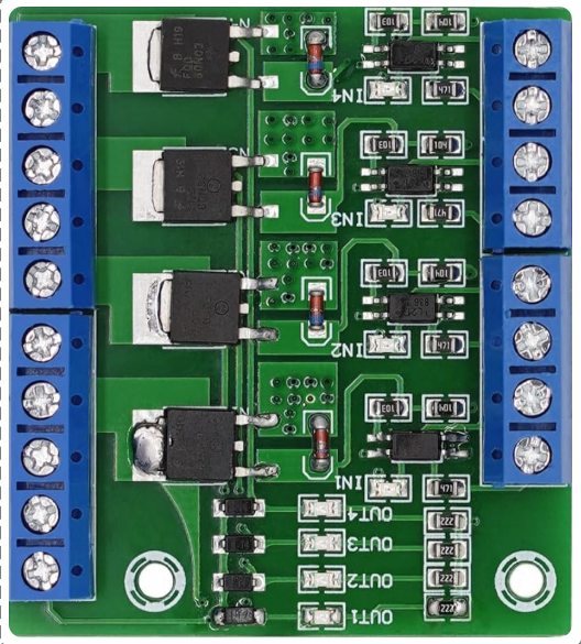
Pin Configuration and Descriptions
The ME60N03 features a 16-pin configuration. The table below describes each pin:
| Pin Number | Pin Name | Description |
|---|---|---|
| 1 | IN1 | Input signal for Channel 1 |
| 2 | IN2 | Input signal for Channel 2 |
| 3 | IN3 | Input signal for Channel 3 |
| 4 | IN4 | Input signal for Channel 4 |
| 5 | GND | Ground connection |
| 6 | OUT1 | Output for Channel 1 |
| 7 | OUT2 | Output for Channel 2 |
| 8 | OUT3 | Output for Channel 3 |
| 9 | OUT4 | Output for Channel 4 |
| 10 | VCC | Power supply input (3.3V to 20V) |
| 11-16 | NC | No connection (reserved for future use or unused) |
Usage Instructions
How to Use the Component in a Circuit
- Power Supply: Connect the VCC pin to a stable power source within the range of 3.3V to 20V. Ensure the GND pin is connected to the circuit ground.
- Input Signals: Provide logic-level signals (e.g., from a microcontroller) to the IN1, IN2, IN3, and IN4 pins to control the corresponding output channels.
- Output Connections: Connect the OUT1, OUT2, OUT3, and OUT4 pins to the gates of the MOSFETs you wish to drive.
- Load Connection: Ensure the MOSFETs are properly connected to the load and power source as per your application requirements.
- Decoupling Capacitor: Place a decoupling capacitor (e.g., 0.1µF) near the VCC pin to stabilize the power supply.
Important Considerations and Best Practices
- Logic Level Compatibility: Ensure the input signals are within the logic level range of the driver (typically 3.3V or 5V).
- Thermal Management: If operating at high currents, ensure adequate heat dissipation for the MOSFETs and the driver.
- Switching Frequency: Avoid exceeding the maximum switching frequency of 1 MHz to prevent performance degradation.
- Noise Reduction: Use proper grounding and shielding techniques to minimize noise in high-speed switching applications.
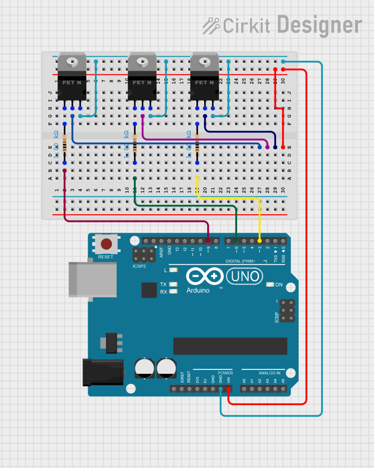
Example: Using with Arduino UNO
The ME60N03 can be easily interfaced with an Arduino UNO to control multiple MOSFETs. Below is an example code to toggle the four channels:
// Define the input pins connected to the ME60N03 driver
#define IN1 3  // Channel 1 input connected to Arduino pin 3
#define IN2 5  // Channel 2 input connected to Arduino pin 5
#define IN3 6  // Channel 3 input connected to Arduino pin 6
#define IN4 9  // Channel 4 input connected to Arduino pin 9

void setup() {
  // Set the input pins as outputs
  pinMode(IN1, OUTPUT);
  pinMode(IN2, OUTPUT);
  pinMode(IN3, OUTPUT);
  pinMode(IN4, OUTPUT);
}

void loop() {
  // Turn on all channels
  digitalWrite(IN1, HIGH);
  digitalWrite(IN2, HIGH);
  digitalWrite(IN3, HIGH);
  digitalWrite(IN4, HIGH);
  delay(1000); // Wait for 1 second

  // Turn off all channels
  digitalWrite(IN1, LOW);
  digitalWrite(IN2, LOW);
  digitalWrite(IN3, LOW);
  digitalWrite(IN4, LOW);
  delay(1000); // Wait for 1 second
}
Troubleshooting and FAQs
Common Issues and Solutions
No Output Signal on Channels
- Cause: Incorrect input signal or power supply connection.
- Solution: Verify the input signals and ensure the VCC and GND pins are properly connected.
Overheating
- Cause: Excessive current or inadequate heat dissipation.
- Solution: Check the load current and ensure proper heat sinks or cooling mechanisms are in place.
Noise or Unstable Operation
- Cause: Poor grounding or insufficient decoupling.
- Solution: Use a decoupling capacitor near the VCC pin and ensure a solid ground connection.
MOSFETs Not Switching Properly
- Cause: Incompatible MOSFET gate threshold voltage.
- Solution: Ensure the MOSFETs used are compatible with the output voltage range of the driver.
FAQs
Q1: Can the ME60N03 drive high-power MOSFETs?
A1: Yes, the ME60N03 can drive high-power MOSFETs as long as the gate charge and voltage requirements are within the driver's output specifications.
Q2: What is the maximum load current per channel?
A2: The ME60N03 can handle up to 3A per channel, but ensure the connected MOSFETs and the circuit are designed to handle the load safely.
Q3: Can I use fewer than four channels?
A3: Yes, unused channels can be left unconnected or tied to ground without affecting the operation of the other channels.
Q4: Is the ME60N03 compatible with 3.3V logic?
A4: Yes, the ME60N03 is compatible with both 3.3V and 5V logic levels, making it suitable for most microcontrollers.