Cirkit Designer Logo
Cirkit Designer
Your all-in-one circuit design IDE
Home / 
Component Documentation

How to Use Mini Boost Module 3.7V to 5V 8V 9V 12V Step Up Board: Examples, Pinouts, and Specs

Image of Mini Boost Module 3.7V to 5V 8V 9V 12V Step Up Board
Cirkit Designer LogoDesign with Mini Boost Module 3.7V to 5V 8V 9V 12V Step Up Board in Cirkit Designer

Introduction

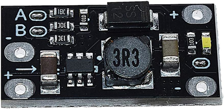
The Mini Boost Module, manufactured by ANMBEST (Part ID: Black), is a compact DC-DC boost converter designed to step up a lower input voltage (3.7V) to a higher output voltage (5V, 8V, 9V, or 12V). This module is commonly used in battery-powered projects to provide a stable higher voltage output, making it ideal for applications such as portable electronics, DIY projects, and any scenario where a higher voltage is required from a lower voltage source.

Explore Projects Built with Mini Boost Module 3.7V to 5V 8V 9V 12V Step Up Board

Use Cirkit Designer to design, explore, and prototype these projects online. Some projects support real-time simulation. Click "Open Project" to start designing instantly!
Battery-Powered 18650 Li-ion Charger with USB Output and Adjustable Voltage Regulator
Image of Breadboard: A project utilizing Mini Boost Module 3.7V to 5V 8V 9V 12V Step Up Board in a practical application
This circuit is a battery management and power supply system that uses three 3.7V batteries connected to a 3S 10A Li-ion 18650 Charger Protection Board Module for balanced charging and protection. The system includes a TP4056 Battery Charging Protection Module for additional charging safety, a Step Up Boost Power Converter to regulate and boost the voltage, and a USB regulator to provide a stable 5V output, controlled by a push switch.
Cirkit Designer LogoOpen Project in Cirkit Designer
Battery-Powered Lora G2 Node Station with 18650 Li-ion Batteries and Boost Converter
Image of Custom-Lora-G2-Node: A project utilizing Mini Boost Module 3.7V to 5V 8V 9V 12V Step Up Board in a practical application
This circuit is a portable power supply system that uses multiple 18650 Li-ion batteries to provide a stable 5V output through a boost converter. It includes a fast charging module with a USB-C input for recharging the batteries and a battery indicator for monitoring the battery status. The system powers a Lora G2 Node Station, making it suitable for wireless communication applications.
Cirkit Designer LogoOpen Project in Cirkit Designer
Battery-Powered High Voltage Generator with Copper Coil
Image of Ionic Thruster Mark_1: A project utilizing Mini Boost Module 3.7V to 5V 8V 9V 12V Step Up Board in a practical application
This circuit consists of a Li-ion battery connected to a step-up power module through a rocker switch, which boosts the voltage to power a ring of copper gauge with an aluminum frame. The rocker switch allows the user to control the power flow from the battery to the step-up module, which then supplies the boosted voltage to the copper ring.
Cirkit Designer LogoOpen Project in Cirkit Designer
Voltage Regulation System with MT3608 Boost and LM2596 Buck Converters
Image of solar system router ups: A project utilizing Mini Boost Module 3.7V to 5V 8V 9V 12V Step Up Board in a practical application
This circuit consists of two MT3608 boost converters and an LM2596 step-down module, each connected to separate 12V power supplies. The MT3608 modules are configured to step up the voltage from their respective power supplies, while the LM2596 module steps down the voltage from a 12V battery. Diodes are used to ensure correct current flow direction, potentially for protection or isolation between different parts of the circuit.
Cirkit Designer LogoOpen Project in Cirkit Designer

Explore Projects Built with Mini Boost Module 3.7V to 5V 8V 9V 12V Step Up Board

Use Cirkit Designer to design, explore, and prototype these projects online. Some projects support real-time simulation. Click "Open Project" to start designing instantly!
Image of Breadboard: A project utilizing Mini Boost Module 3.7V to 5V 8V 9V 12V Step Up Board in a practical application
Battery-Powered 18650 Li-ion Charger with USB Output and Adjustable Voltage Regulator
This circuit is a battery management and power supply system that uses three 3.7V batteries connected to a 3S 10A Li-ion 18650 Charger Protection Board Module for balanced charging and protection. The system includes a TP4056 Battery Charging Protection Module for additional charging safety, a Step Up Boost Power Converter to regulate and boost the voltage, and a USB regulator to provide a stable 5V output, controlled by a push switch.
Cirkit Designer LogoOpen Project in Cirkit Designer
Image of Custom-Lora-G2-Node: A project utilizing Mini Boost Module 3.7V to 5V 8V 9V 12V Step Up Board in a practical application
Battery-Powered Lora G2 Node Station with 18650 Li-ion Batteries and Boost Converter
This circuit is a portable power supply system that uses multiple 18650 Li-ion batteries to provide a stable 5V output through a boost converter. It includes a fast charging module with a USB-C input for recharging the batteries and a battery indicator for monitoring the battery status. The system powers a Lora G2 Node Station, making it suitable for wireless communication applications.
Cirkit Designer LogoOpen Project in Cirkit Designer
Image of Ionic Thruster Mark_1: A project utilizing Mini Boost Module 3.7V to 5V 8V 9V 12V Step Up Board in a practical application
Battery-Powered High Voltage Generator with Copper Coil
This circuit consists of a Li-ion battery connected to a step-up power module through a rocker switch, which boosts the voltage to power a ring of copper gauge with an aluminum frame. The rocker switch allows the user to control the power flow from the battery to the step-up module, which then supplies the boosted voltage to the copper ring.
Cirkit Designer LogoOpen Project in Cirkit Designer
Image of solar system router ups: A project utilizing Mini Boost Module 3.7V to 5V 8V 9V 12V Step Up Board in a practical application
Voltage Regulation System with MT3608 Boost and LM2596 Buck Converters
This circuit consists of two MT3608 boost converters and an LM2596 step-down module, each connected to separate 12V power supplies. The MT3608 modules are configured to step up the voltage from their respective power supplies, while the LM2596 module steps down the voltage from a 12V battery. Diodes are used to ensure correct current flow direction, potentially for protection or isolation between different parts of the circuit.
Cirkit Designer LogoOpen Project in Cirkit Designer

Technical Specifications

Key Technical Details

Parameter Value
Input Voltage 3.7V
Output Voltage 5V, 8V, 9V, 12V (selectable via jumper)
Output Current Up to 1A (depending on input voltage)
Efficiency Up to 92%
Dimensions 22mm x 17mm x 4mm
Operating Temperature -40°C to 85°C

Pin Configuration and Descriptions

Pin Number Pin Name Description
1 VIN Input voltage (3.7V)
2 GND Ground
3 VOUT Output voltage (5V, 8V, 9V, or 12V)

Usage Instructions

How to Use the Component in a Circuit

  1. Connect the Input Voltage:

    • Connect the VIN pin to the positive terminal of your 3.7V power source.
    • Connect the GND pin to the ground terminal of your power source.
  2. Select the Desired Output Voltage:

    • Use the onboard jumper to select the desired output voltage (5V, 8V, 9V, or 12V).
  3. Connect the Output Voltage:

    • Connect the VOUT pin to the positive terminal of the load that requires the higher voltage.
    • Ensure the GND pin is also connected to the ground of the load.

Important Considerations and Best Practices

  • Heat Dissipation: Ensure adequate ventilation or heat sinking if the module is used at high currents to prevent overheating.
  • Input Voltage: The input voltage should be stable and within the specified range (3.7V) to ensure proper operation.
  • Load Requirements: Verify that the load does not exceed the maximum output current capability of the module.

Example Code for Arduino UNO

Here is an example of how to use the Mini Boost Module with an Arduino UNO to power a 12V device:

// Example code to power a 12V device using the Mini Boost Module
// Connect the Mini Boost Module's VOUT to the 12V device
// Connect the GND of the Mini Boost Module to the Arduino GND

void setup() {
  // Initialize serial communication for debugging
  Serial.begin(9600);
  Serial.println("Mini Boost Module Example");
}

void loop() {
  // Your main code here
  // For example, you can control a 12V relay or motor
  // Ensure the Mini Boost Module is providing the correct voltage
  Serial.println("Running...");
  delay(1000); // Wait for 1 second
}

Troubleshooting and FAQs

Common Issues Users Might Face

  1. No Output Voltage:

    • Solution: Check the input voltage connection and ensure it is within the specified range (3.7V). Verify the jumper setting for the desired output voltage.
  2. Overheating:

    • Solution: Ensure proper ventilation and consider adding a heat sink if the module is used at high currents.
  3. Output Voltage Fluctuations:

    • Solution: Verify that the input voltage is stable and not dropping under load. Check for loose connections.

FAQs

Q1: Can I use this module with a different input voltage?

  • A1: The module is designed for a 3.7V input. Using a different input voltage may result in improper operation or damage.

Q2: How do I change the output voltage?

  • A2: Use the onboard jumper to select the desired output voltage (5V, 8V, 9V, or 12V).

Q3: What is the maximum output current?

  • A3: The maximum output current is up to 1A, depending on the input voltage and load conditions.

By following this documentation, users can effectively utilize the Mini Boost Module in their projects, ensuring reliable and stable voltage conversion.