
How to Use VL53L0X: Examples, Pinouts, and Specs
 Design with VL53L0X in Cirkit Designer
Introduction
The VL53L0X is a time-of-flight (ToF) distance sensor that uses laser technology to measure distances with high accuracy. It can measure distances up to 2 meters and is designed to provide precise and reliable results. This compact and low-power sensor is ideal for applications such as robotics, drones, proximity sensing, and gesture recognition. Its small size and advanced features make it a popular choice for projects requiring accurate distance measurements.
Explore Projects Built with VL53L0X
 Open Project in Cirkit Designer
 Open Project in Cirkit Designer
 Open Project in Cirkit Designer
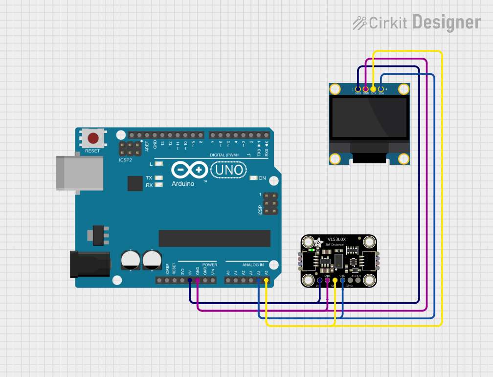 Open Project in Cirkit Designer
Explore Projects Built with VL53L0X
Open Project in Cirkit DesignerOpen Project in Cirkit DesignerOpen Project in Cirkit DesignerOpen Project in Cirkit DesignerTechnical Specifications
- Measurement Range: 30 mm to 2000 mm (2 meters)
- Accuracy: ±3% under optimal conditions
- Operating Voltage: 2.6 V to 3.5 V (logic level compatible with 3.3 V systems)
- Current Consumption:
- Active mode: ~20 mA
- Standby mode: ~5 µA
- Communication Interface: I²C (up to 400 kHz)
- Field of View (FoV): ~25°
- Operating Temperature: -20°C to +70°C
- Dimensions: 4.4 mm x 2.4 mm x 1.0 mm
Pin Configuration and Descriptions
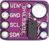
The VL53L0X sensor typically comes in a breakout board format. Below is the pin configuration:
| Pin Name | Description |
|---|---|
| VIN | Power supply input (2.6 V to 5 V). Internally regulated to 2.8 V for the sensor. |
| GND | Ground connection. |
| SDA | I²C data line. Used for communication with the microcontroller. |
| SCL | I²C clock line. Used for communication with the microcontroller. |
| XSHUT | Shutdown pin. Pull low to put the sensor in shutdown mode. |
| GPIO1 | Interrupt output pin (optional, configurable). |
Usage Instructions
How to Use the VL53L0X in a Circuit
- Power Supply: Connect the VIN pin to a 3.3 V or 5 V power source and GND to ground.
- I²C Communication: Connect the SDA and SCL pins to the corresponding I²C pins on your microcontroller. Use pull-up resistors (typically 4.7 kΩ) on the SDA and SCL lines if not already present on the breakout board.
- Optional Pins:
- Connect the XSHUT pin to a GPIO pin on your microcontroller if you need to control the sensor's power state.
- Use the GPIO1 pin if you want to configure and use interrupts.
- Initialization: Use an appropriate library or write custom I²C code to initialize the sensor and configure its settings.
Important Considerations and Best Practices
- Avoid Direct Exposure to Sunlight: The sensor's performance may degrade under strong ambient light.
- Mounting: Ensure the sensor is mounted securely and aligned properly for accurate measurements.
- I²C Address: The default I²C address of the VL53L0X is
0x29. If using multiple sensors, you must change their addresses by toggling the XSHUT pin during initialization. - Distance Limitations: The sensor performs best within its specified range (30 mm to 2 meters). Objects outside this range may result in inaccurate readings.
Example Code for Arduino UNO
Below is an example of how to use the VL53L0X with an Arduino UNO. This code uses the Adafruit VL53L0X library, which simplifies communication with the sensor.
#include <Wire.h>
#include <Adafruit_VL53L0X.h>

// Create an instance of the VL53L0X sensor
Adafruit_VL53L0X lox = Adafruit_VL53L0X();

void setup() {
  Serial.begin(9600); // Initialize serial communication for debugging
  while (!Serial) {
    delay(10); // Wait for the serial connection to be established
  }

  Serial.println("VL53L0X Test");

  // Initialize the sensor
  if (!lox.begin()) {
    Serial.println("Failed to initialize VL53L0X! Check wiring.");
    while (1); // Halt execution if initialization fails
  }
}

void loop() {
  VL53L0X_RangingMeasurementData_t measure;

  // Perform a distance measurement
  lox.rangingTest(&measure, false);

  // Check if the measurement is valid
  if (measure.RangeStatus != 4) { // 4 indicates an out-of-range error
    Serial.print("Distance (mm): ");
    Serial.println(measure.RangeMilliMeter);
  } else {
    Serial.println("Out of range");
  }

  delay(100); // Wait 100 ms before the next measurement
}
Troubleshooting and FAQs
Common Issues
Sensor Not Detected on I²C Bus:
- Ensure the SDA and SCL lines are connected correctly.
- Verify that pull-up resistors are present on the I²C lines.
- Check the sensor's power supply and ensure it is within the specified range.
Inaccurate Distance Measurements:
- Ensure the sensor is not exposed to strong ambient light or reflective surfaces.
- Verify that the object being measured is within the sensor's range (30 mm to 2 meters).
Multiple Sensors on the Same I²C Bus:
- Use the XSHUT pin to change the I²C address of each sensor during initialization.
Solutions and Tips for Troubleshooting
- Debugging I²C Communication: Use an I²C scanner sketch to verify the sensor's address.
- Testing the Sensor: Use a known distance to test the sensor's accuracy and calibrate if necessary.
- Library Issues: Ensure you are using the latest version of the Adafruit VL53L0X library or an equivalent library compatible with your microcontroller.
By following this documentation, you should be able to successfully integrate and use the VL53L0X sensor in your projects.