How to Use Wireless charging module transmitter: Examples, Pinouts, and Specs
Introduction
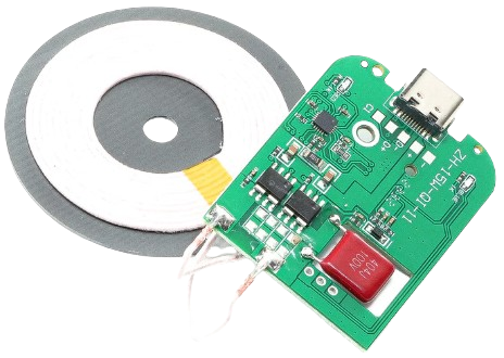
The Wireless Charging Module Transmitter is a device designed to transmit power wirelessly to a compatible receiver. It enables the charging of devices without the need for physical connectors, making it ideal for applications where convenience, durability, and water resistance are priorities. This module is commonly used in consumer electronics, such as smartphones, smartwatches, and other portable devices, as well as in industrial and medical equipment.
Explore Projects Built with Wireless charging module transmitter
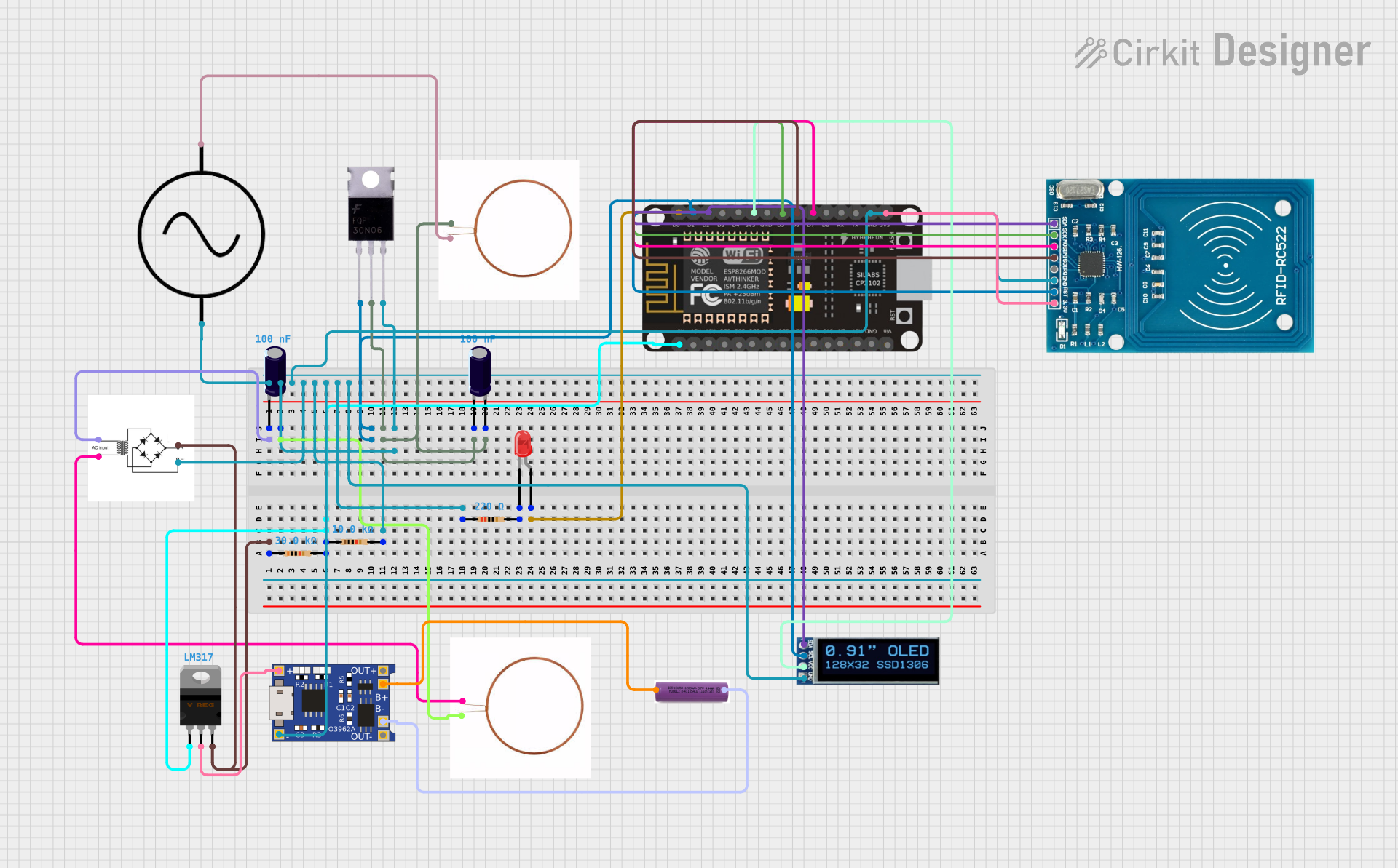


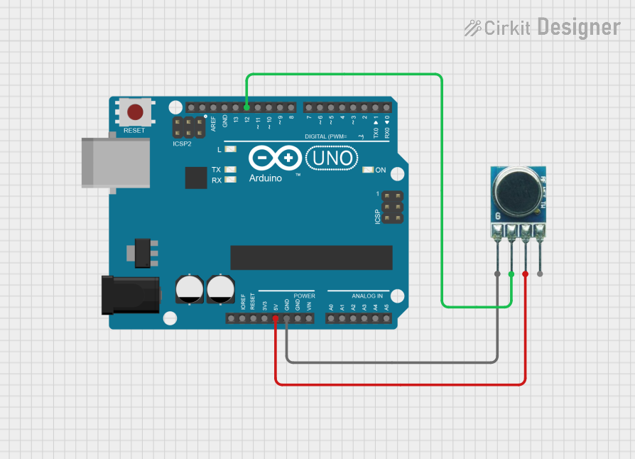
Explore Projects Built with Wireless charging module transmitter
Common Applications and Use Cases
- Wireless charging pads for smartphones and wearables
- Embedded wireless charging in furniture (e.g., desks, tables)
- Medical devices requiring sealed enclosures
- Industrial tools and equipment with ruggedized designs
- IoT devices with limited access to charging ports
Technical Specifications
Key Technical Details
| Parameter | Value |
|---|---|
| Input Voltage | 5V to 12V DC |
| Output Power | Up to 10W (depending on receiver) |
| Operating Frequency | 110 kHz to 205 kHz |
| Efficiency | Up to 85% |
| Transmission Distance | 2 mm to 8 mm |
| Coil Type | Single or multi-coil configuration |
| Dimensions | Varies by model (e.g., 40mm x 40mm) |
| Operating Temperature | -10°C to 50°C |
Pin Configuration and Descriptions
| Pin Number | Pin Name | Description |
|---|---|---|
| 1 | VCC | Power input (5V to 12V DC) |
| 2 | GND | Ground connection |
| 3 | TX Coil+ | Positive terminal of the transmitter coil |
| 4 | TX Coil- | Negative terminal of the transmitter coil |
| 5 | EN (Enable) | Enable pin to activate or deactivate the module |
| 6 | STATUS | Status output pin (indicates charging activity) |
Usage Instructions
How to Use the Component in a Circuit
- Power Supply: Connect the
VCCpin to a stable DC power source (5V to 12V) and theGNDpin to ground. - Coil Connection: Attach the transmitter coil to the
TX Coil+andTX Coil-pins. Ensure the coil is properly aligned and secured. - Enable Pin: Use the
ENpin to control the module. Pull it high (logic 1) to enable the transmitter or low (logic 0) to disable it. - Receiver Alignment: Place the compatible receiver device within the transmission range (2 mm to 8 mm) for optimal charging performance.
- Status Monitoring: Use the
STATUSpin to monitor charging activity. This pin typically outputs a high signal when charging is active.
Important Considerations and Best Practices
- Alignment: Ensure proper alignment between the transmitter and receiver coils for maximum efficiency.
- Distance: Maintain the recommended transmission distance (2 mm to 8 mm) to avoid power loss or overheating.
- Heat Management: Provide adequate ventilation or heat dissipation to prevent the module from overheating during prolonged use.
- Power Supply: Use a regulated power supply to avoid voltage fluctuations that could damage the module.
- Interference: Avoid placing metal objects between the transmitter and receiver, as they can interfere with power transmission.
Example: Using with an Arduino UNO
The Wireless Charging Module Transmitter can be controlled using an Arduino UNO to enable or disable charging based on specific conditions. Below is an example code snippet:
// Define pin connections
const int enablePin = 7;  // Pin connected to the EN (Enable) pin of the module
const int statusPin = 8;  // Pin connected to the STATUS pin of the module

void setup() {
  pinMode(enablePin, OUTPUT);  // Set the enable pin as an output
  pinMode(statusPin, INPUT);   // Set the status pin as an input

  // Start with the transmitter disabled
  digitalWrite(enablePin, LOW);
}

void loop() {
  // Example: Enable the transmitter for 10 seconds, then disable it
  digitalWrite(enablePin, HIGH);  // Enable the transmitter
  delay(10000);                   // Wait for 10 seconds
  digitalWrite(enablePin, LOW);   // Disable the transmitter
  delay(5000);                    // Wait for 5 seconds before repeating

  // Optional: Monitor the STATUS pin
  int status = digitalRead(statusPin);
  if (status == HIGH) {
    // Charging is active
    Serial.println("Charging in progress...");
  } else {
    // Charging is not active
    Serial.println("No charging activity.");
  }
}
Troubleshooting and FAQs
Common Issues and Solutions
No Power Transmission
- Cause: Incorrect power supply or loose connections.
- Solution: Verify the input voltage (5V to 12V) and ensure all connections are secure.
Overheating
- Cause: Prolonged use without proper ventilation or excessive transmission distance.
- Solution: Reduce the transmission distance and provide adequate cooling.
Low Efficiency
- Cause: Misalignment between the transmitter and receiver coils.
- Solution: Adjust the alignment to ensure the coils are properly centered.
Interference from Metal Objects
- Cause: Metal objects between the transmitter and receiver.
- Solution: Remove any metal objects from the charging area.
Module Not Responding
- Cause: Enable pin not properly configured.
- Solution: Check the
ENpin connection and ensure it is pulled high to activate the module.
FAQs
Can this module charge any device?
- No, the receiver device must be compatible with the module's operating frequency and power output.
What happens if the transmission distance exceeds 8 mm?
- The efficiency drops significantly, and the device may not charge.
Can I use this module outdoors?
- The module itself is not weatherproof. Use a protective enclosure for outdoor applications.
Is it safe to leave the module powered on continuously?
- Yes, but ensure proper heat dissipation to prevent overheating during extended use.
Can I use multiple transmitter coils?
- Yes, some modules support multi-coil configurations for larger charging areas. Check the module's specifications.