How to Use TDSSS: Examples, Pinouts, and Specs
Introduction
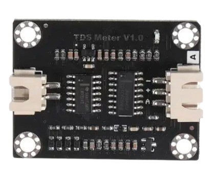
The TDSSS (Time Domain Signal Sampling System), manufactured by Arduino (Part ID: TDSS), is a specialized circuit component designed for sampling and processing time-domain signals. It is widely used in signal processing and data acquisition systems, where precise and efficient signal sampling is critical. The TDSSS is ideal for applications requiring high-speed data acquisition, real-time signal analysis, and digital signal processing.
Explore Projects Built with TDSSS
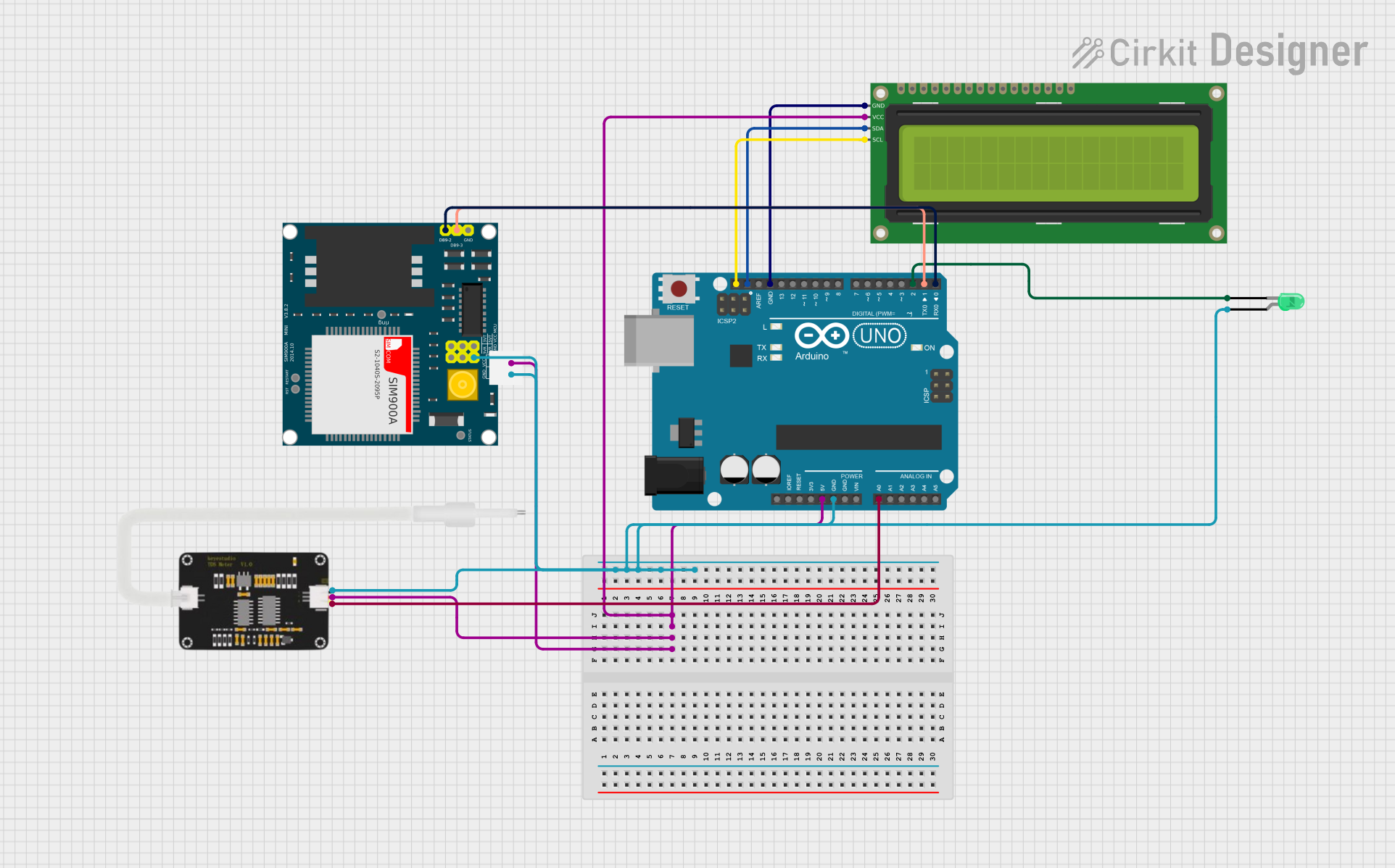

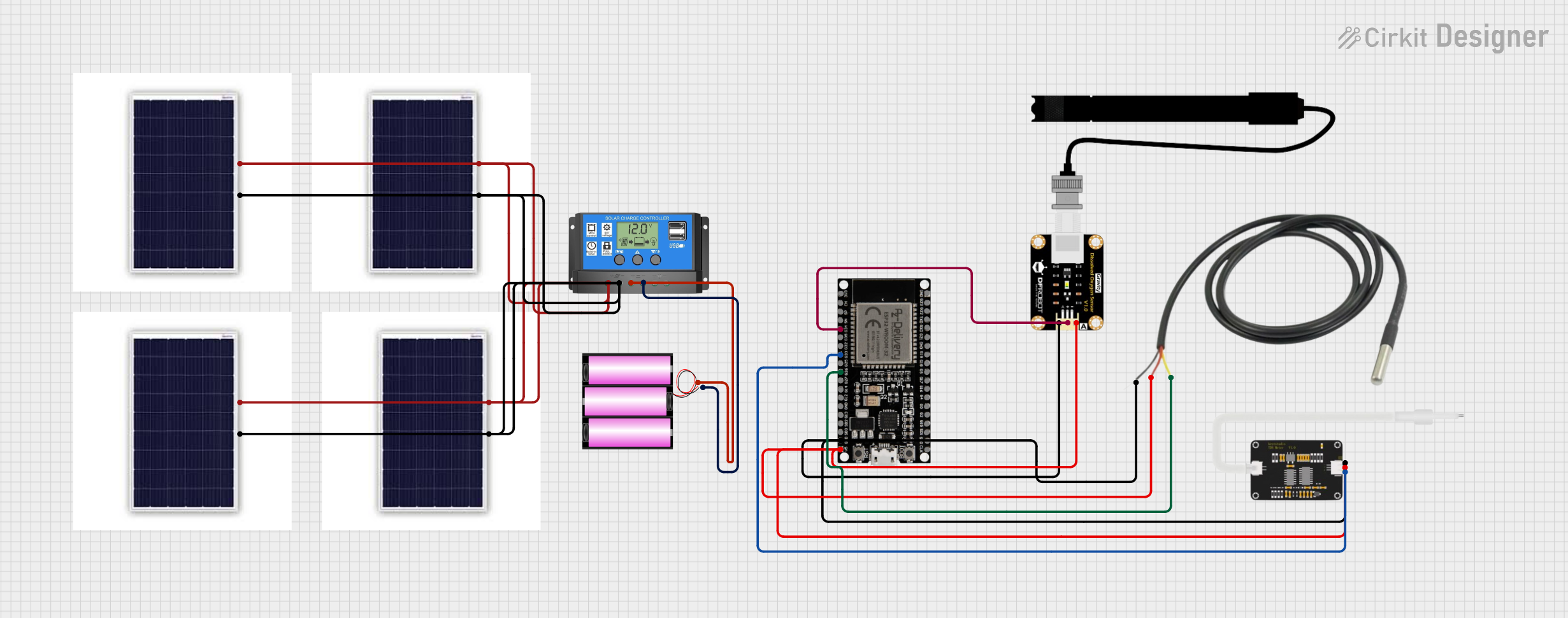
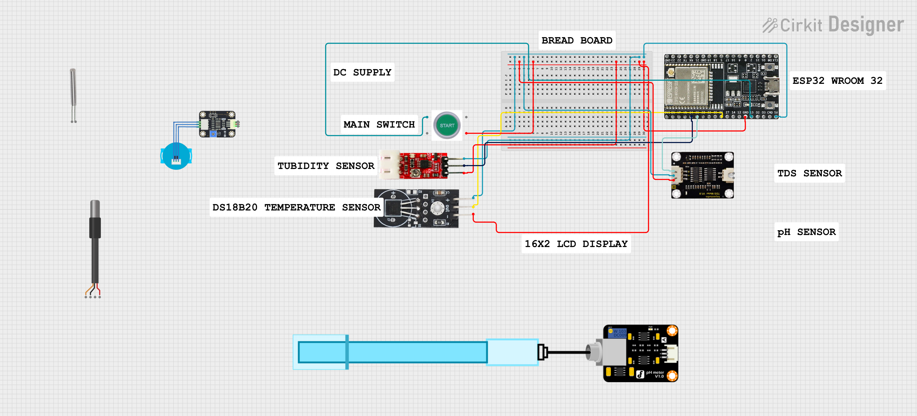
Explore Projects Built with TDSSS
Common Applications
- Oscilloscopes and signal analyzers
- Data acquisition systems
- Real-time signal processing
- Audio and video signal sampling
- Embedded systems requiring precise signal measurements
Technical Specifications
Key Technical Details
| Parameter | Value |
|---|---|
| Manufacturer | Arduino |
| Part ID | TDSS |
| Operating Voltage | 3.3V to 5V |
| Sampling Rate | Up to 1 MSPS (Mega Samples Per Second) |
| Input Signal Range | 0V to 3.3V |
| Resolution | 12-bit |
| Power Consumption | 50 mW (typical) |
| Operating Temperature | -40°C to +85°C |
| Communication Protocol | SPI (Serial Peripheral Interface) |
Pin Configuration and Descriptions
| Pin Number | Pin Name | Description |
|---|---|---|
| 1 | VCC | Power supply input (3.3V to 5V). |
| 2 | GND | Ground connection. |
| 3 | IN+ | Positive input for the signal to be sampled. |
| 4 | IN- | Negative input for differential signal sampling (optional). |
| 5 | CS | Chip Select pin for SPI communication. |
| 6 | SCLK | Serial Clock input for SPI communication. |
| 7 | MISO | Master In Slave Out - Data output for SPI communication. |
| 8 | MOSI | Master Out Slave In - Data input for SPI communication (optional). |
| 9 | DRDY | Data Ready - Indicates when a new sample is available. |
| 10 | RESET | Resets the component to its default state. |
Usage Instructions
How to Use the TDSSS in a Circuit
- Power Supply: Connect the VCC pin to a 3.3V or 5V power source and the GND pin to the ground.
- Signal Input: Connect the signal to be sampled to the IN+ pin. For differential signals, connect the complementary signal to the IN- pin.
- SPI Communication:
- Connect the CS, SCLK, and MISO pins to the corresponding SPI pins on your microcontroller.
- If required, connect the MOSI pin for bidirectional communication.
- Data Ready Signal: Use the DRDY pin to monitor when a new sample is available for reading.
- Reset: Optionally, connect the RESET pin to a GPIO pin on your microcontroller for resetting the component.
Important Considerations and Best Practices
- Ensure the input signal does not exceed the specified range (0V to 3.3V) to avoid damage.
- Use decoupling capacitors (e.g., 0.1 µF) near the VCC pin to reduce noise.
- For optimal performance, use shielded cables for signal input and minimize the length of SPI connections.
- Configure the SPI clock speed according to the TDSSS's specifications to ensure reliable communication.
Example Code for Arduino UNO
Below is an example of how to interface the TDSSS with an Arduino UNO using SPI:
#include <SPI.h>

// Define pin connections
const int CS_PIN = 10;  // Chip Select pin
const int DRDY_PIN = 2; // Data Ready pin

void setup() {
  // Initialize SPI communication
  SPI.begin();
  pinMode(CS_PIN, OUTPUT);
  pinMode(DRDY_PIN, INPUT);
  digitalWrite(CS_PIN, HIGH); // Set CS pin to HIGH (inactive)

  Serial.begin(9600); // Initialize serial communication for debugging
}

void loop() {
  // Wait for the Data Ready signal
  if (digitalRead(DRDY_PIN) == LOW) {
    digitalWrite(CS_PIN, LOW); // Activate the TDSSS by pulling CS LOW

    // Read 2 bytes of data (12-bit resolution)
    uint16_t sample = SPI.transfer(0x00) << 8; // Read high byte
    sample |= SPI.transfer(0x00);             // Read low byte

    digitalWrite(CS_PIN, HIGH); // Deactivate the TDSSS by pulling CS HIGH

    // Print the sampled value
    Serial.println(sample);
  }
}
Notes:
- Ensure the SPI clock speed is set to a value supported by the TDSSS (e.g., 1 MHz).
- The
DRDY_PINis used to detect when a new sample is ready for reading.
Troubleshooting and FAQs
Common Issues and Solutions
No Data Output
- Ensure the SPI connections (CS, SCLK, MISO) are correctly wired.
- Verify that the power supply voltage is within the specified range (3.3V to 5V).
- Check if the DRDY pin is toggling to indicate new data availability.
Corrupted or Inaccurate Data
- Ensure the input signal is within the specified range (0V to 3.3V).
- Use proper grounding and shielding to minimize noise interference.
- Verify the SPI clock speed and ensure it matches the TDSSS's requirements.
Component Overheating
- Check for excessive input voltage or current.
- Ensure proper ventilation and avoid operating the component beyond its temperature range.
FAQs
Q: Can the TDSSS handle differential signals?
A: Yes, the TDSSS supports differential signal sampling using the IN+ and IN- pins.
Q: What is the maximum sampling rate of the TDSSS?
A: The TDSSS supports a maximum sampling rate of 1 MSPS (Mega Samples Per Second).
Q: Is the TDSSS compatible with 5V logic levels?
A: Yes, the TDSSS is compatible with both 3.3V and 5V logic levels.
Q: How do I reset the TDSSS?
A: You can reset the TDSSS by toggling the RESET pin or cycling the power supply.
This documentation provides a comprehensive guide to using the TDSSS effectively in your projects. For further assistance, refer to the Arduino support resources.