
How to Use ADXL345: Examples, Pinouts, and Specs
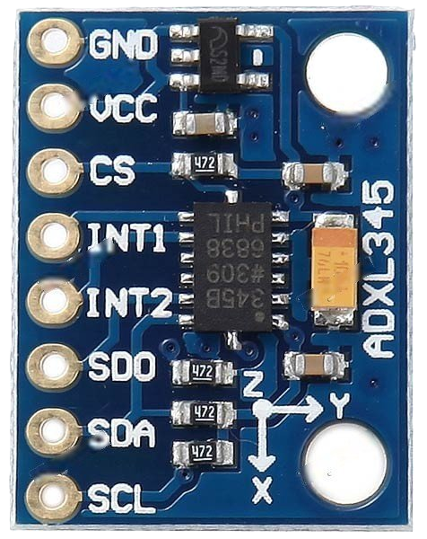
 Design with ADXL345 in Cirkit Designer
Introduction
The ADXL345 is a small, thin, low-power, 3-axis accelerometer with a digital output, manufactured by Adafruit (Part ID: ADXL345). It is designed to measure acceleration in three dimensions (X, Y, and Z axes) and is widely used in applications requiring motion sensing and tilt detection. The device communicates via I2C or SPI interfaces, making it versatile and easy to integrate into various systems.
Explore Projects Built with ADXL345
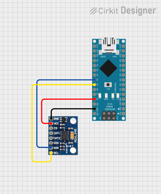 Open Project in Cirkit Designer
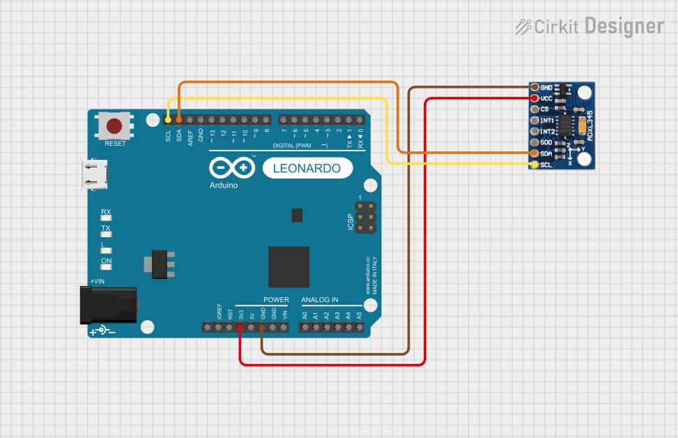 Open Project in Cirkit Designer
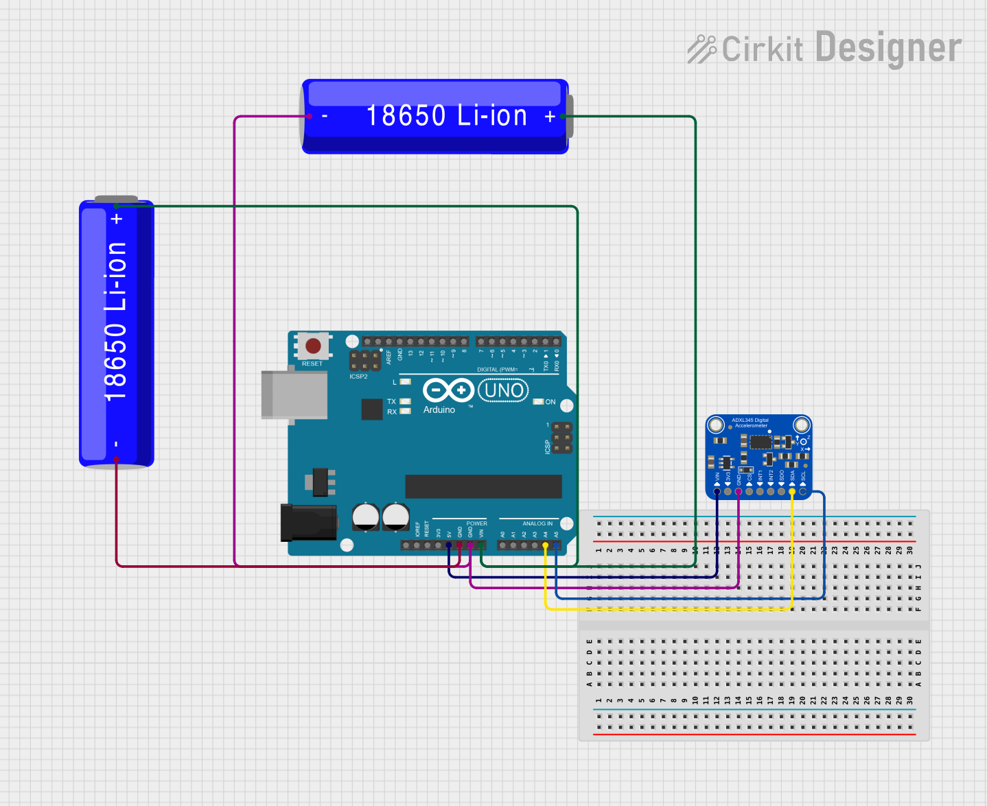 Open Project in Cirkit Designer
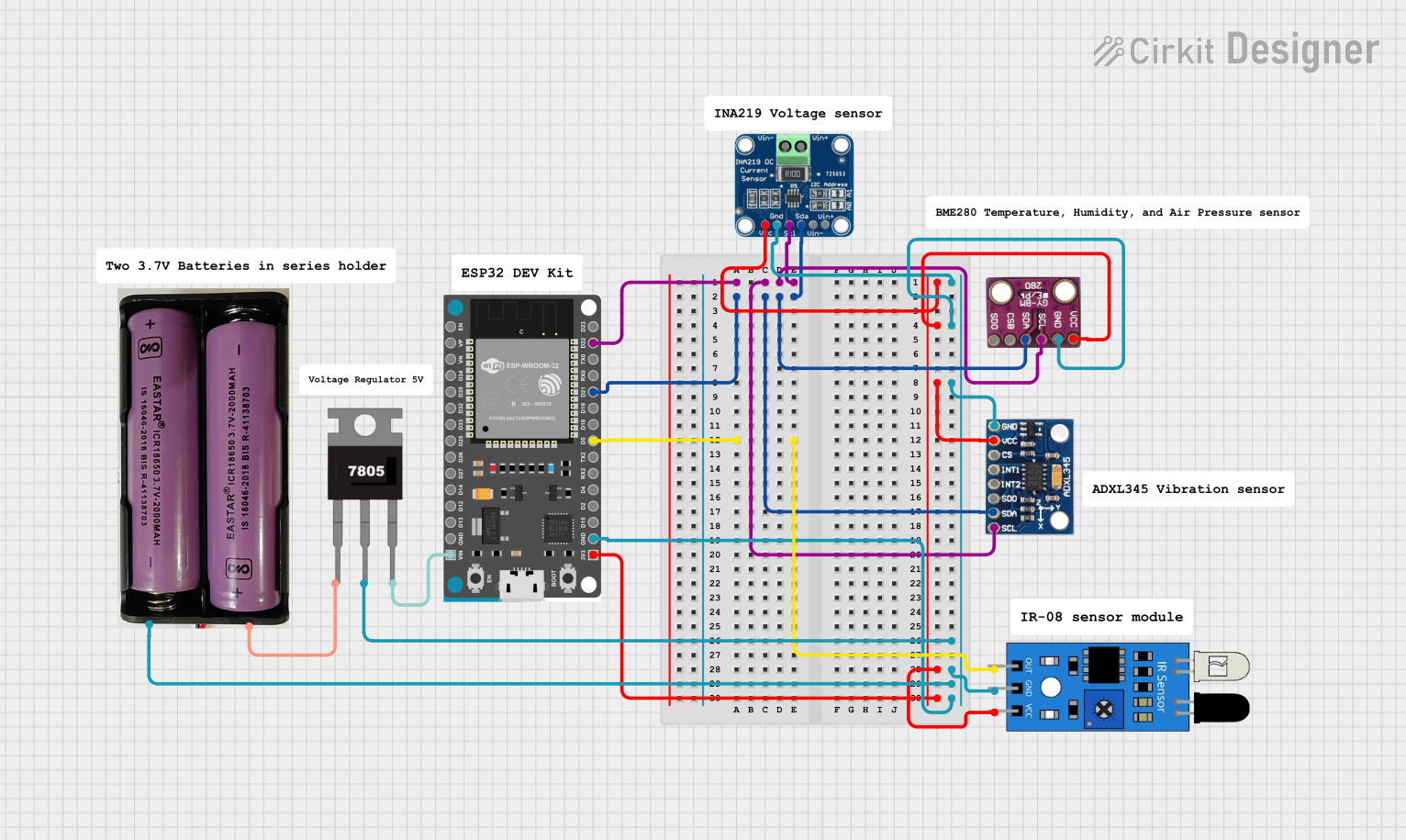 Open Project in Cirkit Designer
Explore Projects Built with ADXL345
Open Project in Cirkit DesignerOpen Project in Cirkit DesignerOpen Project in Cirkit DesignerOpen Project in Cirkit DesignerCommon Applications
- Mobile devices for screen orientation and motion detection
- Wearable technology for fitness tracking and activity monitoring
- Robotics for motion sensing and navigation
- Gaming devices for gesture recognition
- Industrial equipment for vibration monitoring
Technical Specifications
The ADXL345 offers a range of features and specifications that make it suitable for a variety of applications. Below are the key technical details:
| Parameter | Value |
|---|---|
| Supply Voltage (VDD) | 2.0V to 3.6V |
| I/O Voltage (VDDIO) | 1.7V to VDD |
| Power Consumption | 40 µA in measurement mode, 0.1 µA in standby |
| Measurement Range | ±2g, ±4g, ±8g, ±16g (selectable) |
| Output Data Rate (ODR) | 0.1 Hz to 3200 Hz |
| Communication Interface | I2C (up to 400 kHz) or SPI (up to 5 MHz) |
| Operating Temperature | -40°C to +85°C |
| Dimensions | 3 mm × 5 mm × 1 mm |
Pin Configuration
The ADXL345 has 8 pins, each with a specific function. The table below describes the pin configuration:
| Pin | Name | Description |
|---|---|---|
| 1 | VDD | Power supply (2.0V to 3.6V) |
| 2 | GND | Ground |
| 3 | CS | Chip Select (SPI mode) or I2C Address Select (I2C mode) |
| 4 | INT1 | Interrupt 1 output |
| 5 | INT2 | Interrupt 2 output |
| 6 | SCL/SCLK | I2C Clock (SCL) or SPI Clock (SCLK) |
| 7 | SDA/SDI/SDO | I2C Data (SDA), SPI Data Input (SDI), or Data Output (SDO) |
| 8 | NC | No Connection |
Usage Instructions
The ADXL345 can be used in either I2C or SPI mode, depending on the application. Below are the steps to integrate the ADXL345 into a circuit and use it effectively:
Circuit Connection
- Power Supply: Connect the VDD pin to a 3.3V power source and the GND pin to ground.
- Communication Interface:
- For I2C mode:
- Connect the SCL pin to the I2C clock line of the microcontroller.
- Connect the SDA pin to the I2C data line of the microcontroller.
- Tie the CS pin to VDD to enable I2C mode.
- For SPI mode:
- Connect the SCLK pin to the SPI clock line of the microcontroller.
- Connect the SDI/SDO pin to the SPI data line.
- Use the CS pin for chip selection.
- For I2C mode:
- Interrupts: Optionally, connect INT1 and/or INT2 to the microcontroller for interrupt-driven applications.
Arduino UNO Example Code
Below is an example of how to use the ADXL345 with an Arduino UNO in I2C mode:
#include <Wire.h> // Include the Wire library for I2C communication

#define ADXL345_ADDRESS 0x53 // I2C address of the ADXL345

void setup() {
  Wire.begin(); // Initialize I2C communication
  Serial.begin(9600); // Start serial communication for debugging

  // Initialize the ADXL345
  Wire.beginTransmission(ADXL345_ADDRESS);
  Wire.write(0x2D); // Power control register
  Wire.write(0x08); // Set measurement mode
  Wire.endTransmission();

  Serial.println("ADXL345 initialized.");
}

void loop() {
  int16_t x, y, z;

  // Request data from the ADXL345
  Wire.beginTransmission(ADXL345_ADDRESS);
  Wire.write(0x32); // Start reading from the DATAX0 register
  Wire.endTransmission(false);
  Wire.requestFrom(ADXL345_ADDRESS, 6); // Request 6 bytes (X, Y, Z data)

  if (Wire.available() == 6) {
    x = Wire.read() | (Wire.read() << 8); // Combine low and high bytes for X
    y = Wire.read() | (Wire.read() << 8); // Combine low and high bytes for Y
    z = Wire.read() | (Wire.read() << 8); // Combine low and high bytes for Z
  }

  // Print the acceleration values
  Serial.print("X: "); Serial.print(x);
  Serial.print(" Y: "); Serial.print(y);
  Serial.print(" Z: "); Serial.println(z);

  delay(500); // Wait for 500ms before the next reading
}
Best Practices
- Use appropriate pull-up resistors (4.7kΩ to 10kΩ) on the SDA and SCL lines for I2C communication.
- Ensure the power supply voltage is within the specified range to avoid damaging the device.
- Use decoupling capacitors (e.g., 0.1 µF) near the VDD pin to reduce noise.
- Configure the measurement range and data rate according to your application requirements.
Troubleshooting and FAQs
Common Issues
No Communication with the ADXL345:
- Ensure the correct I2C address (0x53) is used in the code.
- Verify the wiring connections, especially the SDA and SCL lines.
- Check for proper pull-up resistors on the I2C lines.
Incorrect or No Acceleration Data:
- Confirm that the ADXL345 is in measurement mode (register 0x2D set to 0x08).
- Verify that the data rate and range settings are appropriate for your application.
Device Overheating:
- Ensure the supply voltage does not exceed 3.6V.
- Check for short circuits in the wiring.
FAQs
Q: Can the ADXL345 be used with a 5V microcontroller?
A: Yes, but you must use a logic level shifter to convert the 5V signals to 3.3V for the ADXL345.
Q: How do I change the measurement range?
A: Write to the DATA_FORMAT register (0x31) to set the desired range (±2g, ±4g, ±8g, or ±16g).
Q: What is the maximum sampling rate of the ADXL345?
A: The maximum output data rate (ODR) is 3200 Hz.
By following this documentation, you can effectively integrate and use the ADXL345 in your projects.