How to Use Limit Switch KW12-3: Examples, Pinouts, and Specs
Introduction
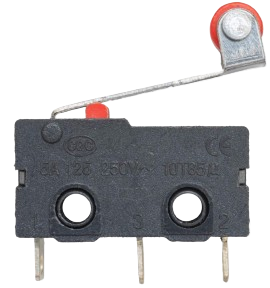
The Limit Switch KW12-3 is a mechanical switch designed to detect the presence, absence, or position of an object. It is widely used in industrial automation, machinery, and safety systems. This compact and durable switch is ideal for applications requiring precise control and reliable operation. The KW12-3 is commonly employed in CNC machines, 3D printers, conveyor systems, and robotic arms to ensure safe and efficient operation.
Explore Projects Built with Limit Switch KW12-3


Explore Projects Built with Limit Switch KW12-3
Technical Specifications
- Model: KW12-3
- Type: SPDT (Single Pole Double Throw)
- Rated Voltage: 250V AC / 125V AC
- Rated Current: 5A
- Contact Resistance: ≤ 50 mΩ
- Insulation Resistance: ≥ 100 MΩ (at 500V DC)
- Mechanical Life: ≥ 1,000,000 cycles
- Electrical Life: ≥ 50,000 cycles
- Operating Force: 50gf to 200gf
- Operating Temperature: -25°C to +85°C
- Mounting Style: Screw or PCB mount
- Dimensions: 20mm x 6.4mm x 10.2mm (approx.)
Pin Configuration and Descriptions
The KW12-3 limit switch has three terminals: Common (COM), Normally Open (NO), and Normally Closed (NC). The table below describes their functions:
| Pin Name | Description |
|---|---|
| COM | Common terminal. Connects to either NO or NC depending on the switch state. |
| NO | Normally Open terminal. Closed when the switch is activated. |
| NC | Normally Closed terminal. Open when the switch is activated. |
Usage Instructions
How to Use the KW12-3 in a Circuit
- Identify the Terminals: Locate the COM, NO, and NC terminals on the switch.
- Connect the Circuit:
- For a circuit that requires activation when the switch is pressed, connect the load between COM and NO.
- For a circuit that requires activation when the switch is released, connect the load between COM and NC.
- Mount the Switch: Secure the switch using screws or solder it onto a PCB, depending on your application.
- Test the Switch: Manually press the actuator to verify the circuit behavior.
Important Considerations and Best Practices
- Debouncing: Mechanical switches like the KW12-3 may produce noise or "bouncing" when activated. Use a capacitor or software debouncing techniques to ensure stable operation.
- Current and Voltage Ratings: Do not exceed the rated voltage (250V AC) or current (5A) to avoid damage or failure.
- Environmental Conditions: Ensure the switch is used within its operating temperature range (-25°C to +85°C) and protected from excessive moisture or dust.
- Mounting: Avoid over-tightening screws to prevent damage to the switch housing.
Example: Connecting the KW12-3 to an Arduino UNO
The KW12-3 can be used with an Arduino UNO to detect the position of an object. Below is an example circuit and code:
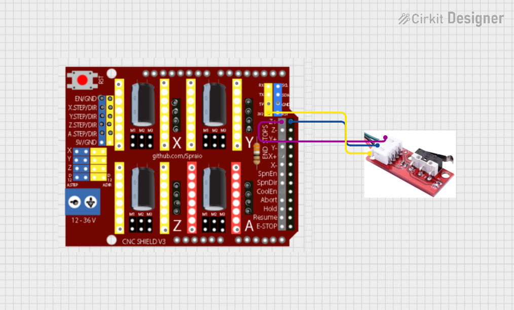
Circuit Diagram
- Connect the COM terminal of the KW12-3 to the GND pin of the Arduino.
- Connect the NO terminal of the KW12-3 to digital pin 2 of the Arduino.
- Use a pull-up resistor (10kΩ) between digital pin 2 and the 5V pin of the Arduino.
Arduino Code
// Example code for using the KW12-3 limit switch with Arduino UNO
const int switchPin = 2; // Pin connected to the NO terminal of the switch
const int ledPin = 13;   // Built-in LED pin on Arduino

void setup() {
  pinMode(switchPin, INPUT_PULLUP); // Set switch pin as input with pull-up resistor
  pinMode(ledPin, OUTPUT);          // Set LED pin as output
  Serial.begin(9600);               // Initialize serial communication
}

void loop() {
  int switchState = digitalRead(switchPin); // Read the state of the switch

  if (switchState == LOW) { // Switch is pressed (NO terminal connected to COM)
    digitalWrite(ledPin, HIGH); // Turn on the LED
    Serial.println("Switch Pressed");
  } else { // Switch is not pressed
    digitalWrite(ledPin, LOW);  // Turn off the LED
    Serial.println("Switch Released");
  }

  delay(100); // Small delay for stability
}
Troubleshooting and FAQs
Common Issues and Solutions
Switch Not Responding:
- Cause: Loose or incorrect wiring.
- Solution: Verify the connections to the COM, NO, and NC terminals. Ensure proper contact.
Unstable or Erratic Behavior:
- Cause: Switch bouncing.
- Solution: Add a capacitor (e.g., 0.1µF) across the switch terminals or implement software debouncing in your code.
Switch Fails to Activate:
- Cause: Mechanical failure or actuator misalignment.
- Solution: Inspect the actuator for damage or obstruction. Replace the switch if necessary.
Overheating or Burnt Contacts:
- Cause: Exceeding voltage or current ratings.
- Solution: Ensure the load does not exceed 250V AC or 5A. Use a relay for high-power applications.
FAQs
Q: Can the KW12-3 be used with DC circuits?
A: Yes, the KW12-3 can be used with DC circuits as long as the voltage and current ratings are not exceeded.Q: How do I mount the KW12-3 on a PCB?
A: The KW12-3 has solderable pins for PCB mounting. Ensure proper alignment and solder securely.Q: Is the KW12-3 waterproof?
A: No, the KW12-3 is not waterproof. Use a protective enclosure for outdoor or wet environments.Q: Can I use the KW12-3 for safety-critical applications?
A: While the KW12-3 is reliable, it is recommended to use certified safety-rated switches for critical applications.