How to Use RELAY SRD-05VDC-SL-C: Examples, Pinouts, and Specs
Introduction
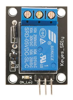
The SRD-05VDC-SL-C is a 5V DC relay module manufactured by SONGLE. It is designed to enable low voltage control signals to switch high voltage devices, making it an essential component in automation, home appliances, and IoT projects. This relay features a Single Pole Double Throw (SPDT) configuration, allowing it to control two circuits (normally open and normally closed) with a single input signal.
Explore Projects Built with RELAY SRD-05VDC-SL-C


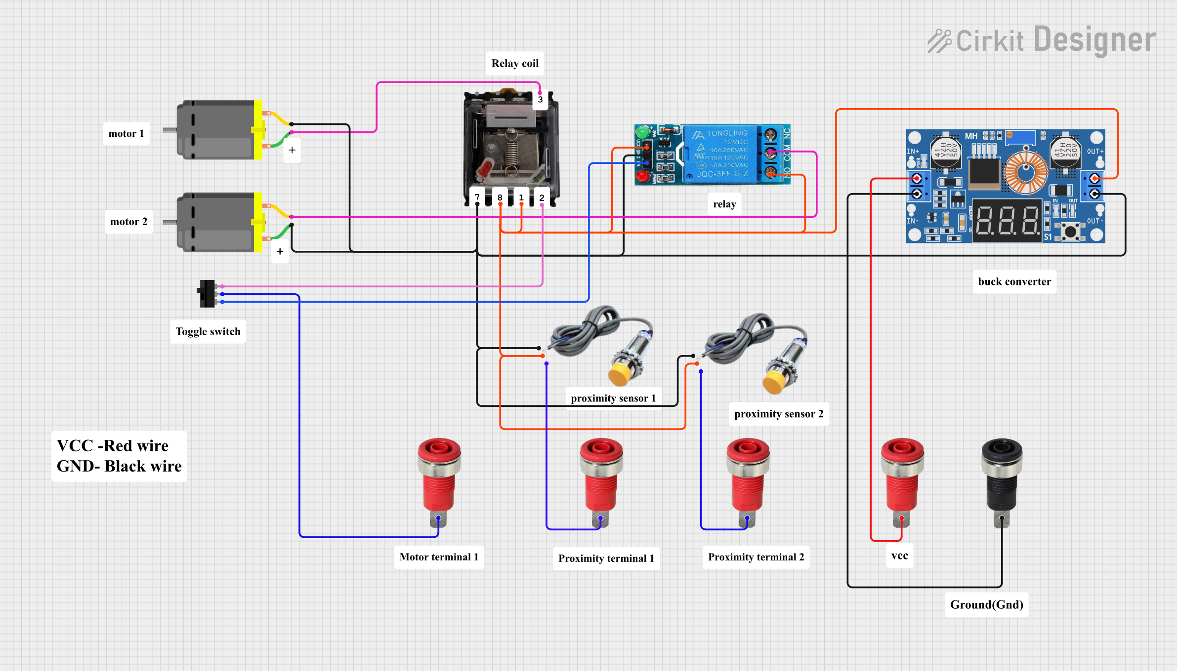
Explore Projects Built with RELAY SRD-05VDC-SL-C
Common Applications
- Home automation systems (e.g., controlling lights, fans, or appliances)
- Industrial control systems
- IoT projects for remote device control
- Motor control and switching
- Safety systems and alarms
Technical Specifications
The SRD-05VDC-SL-C relay is designed for reliable and efficient operation in a variety of applications. Below are its key technical details:
Electrical Specifications
| Parameter | Value |
|---|---|
| Operating Voltage | 5V DC |
| Trigger Voltage | 3.75V DC (minimum) |
| Trigger Current | 70 mA |
| Contact Type | SPDT (Single Pole Double Throw) |
| Contact Rating | 10A @ 250V AC / 10A @ 30V DC |
| Coil Resistance | 70 Ω |
| Max Switching Voltage | 250V AC / 30V DC |
| Max Switching Current | 10A |
| Insulation Resistance | ≥100MΩ (at 500V DC) |
| Dielectric Strength | 500V AC (coil to contact) |
| Operating Temperature | -40°C to +85°C |
| Mechanical Life | 10 million operations |
| Electrical Life | 100,000 operations |
Pin Configuration
The SRD-05VDC-SL-C relay has five pins, as described in the table below:
| Pin Number | Pin Name | Description |
|---|---|---|
| 1 | Coil Positive | Connect to the positive terminal of the 5V DC power supply. |
| 2 | Coil Negative | Connect to the negative terminal (ground) of the 5V DC power supply. |
| 3 | Common (COM) | Common terminal for the relay's switching contacts. |
| 4 | Normally Open (NO) | Open circuit when the relay is inactive; closed when the relay is activated. |
| 5 | Normally Closed (NC) | Closed circuit when the relay is inactive; open when the relay is activated. |
Usage Instructions
How to Use the SRD-05VDC-SL-C in a Circuit
- Power the Relay: Connect the coil positive pin to a 5V DC power source and the coil negative pin to ground.
- Control Signal: Use a microcontroller (e.g., Arduino UNO) or a transistor to provide the trigger signal to the relay.
- Connect the Load:
- Connect the load's power source to the Common (COM) pin.
- Use the Normally Open (NO) pin if you want the load to be powered only when the relay is activated.
- Use the Normally Closed (NC) pin if you want the load to be powered when the relay is inactive.
- Isolation: Ensure proper isolation between the low voltage control circuit and the high voltage load circuit to prevent damage or hazards.
Important Considerations
- Flyback Diode: Always use a flyback diode across the relay coil to protect the control circuit from voltage spikes when the relay is deactivated.
- Current Rating: Ensure the load's current does not exceed the relay's maximum rating of 10A.
- Heat Dissipation: Avoid prolonged operation near the relay's maximum current and voltage ratings to prevent overheating.
- Safety: When switching high voltage AC loads, ensure proper insulation and follow safety guidelines to avoid electric shock.
Example: Connecting the SRD-05VDC-SL-C to an Arduino UNO
Below is an example of how to control the SRD-05VDC-SL-C relay using an Arduino UNO:
// Example: Controlling SRD-05VDC-SL-C relay with Arduino UNO

// Define the pin connected to the relay module
const int relayPin = 7;

void setup() {
  // Set the relay pin as an output
  pinMode(relayPin, OUTPUT);

  // Ensure the relay is off at startup
  digitalWrite(relayPin, LOW);
}

void loop() {
  // Turn the relay on (activates the connected load)
  digitalWrite(relayPin, HIGH);
  delay(5000); // Keep the relay on for 5 seconds

  // Turn the relay off (deactivates the connected load)
  digitalWrite(relayPin, LOW);
  delay(5000); // Keep the relay off for 5 seconds
}
Notes:
- Use a transistor or relay driver circuit if the Arduino's GPIO pin cannot supply sufficient current to the relay.
- Ensure the Arduino and relay module share a common ground.
Troubleshooting and FAQs
Common Issues and Solutions
Relay Not Activating:
- Cause: Insufficient trigger voltage or current.
- Solution: Verify that the control signal provides at least 3.75V and 70 mA.
Load Not Switching:
- Cause: Incorrect wiring of the load to the relay's COM, NO, or NC pins.
- Solution: Double-check the wiring and ensure the load is connected to the correct pins.
Relay Buzzing Noise:
- Cause: Insufficient power supply to the relay coil.
- Solution: Use a stable 5V DC power source with adequate current capacity.
Overheating:
- Cause: Load exceeds the relay's maximum current or voltage rating.
- Solution: Ensure the load is within the relay's rated specifications.
Arduino Resetting When Relay Activates:
- Cause: Voltage spikes from the relay coil affecting the Arduino.
- Solution: Add a flyback diode across the relay coil and use a separate power supply for the relay.
FAQs
Q1: Can I use the SRD-05VDC-SL-C relay with a 3.3V microcontroller?
A1: Yes, but you will need a transistor or relay driver circuit to amplify the 3.3V signal to 5V.
Q2: Is the relay suitable for switching DC motors?
A2: Yes, as long as the motor's voltage and current are within the relay's rated specifications.
Q3: Can I use the relay to switch both AC and DC loads?
A3: Yes, the relay supports both AC (up to 250V) and DC (up to 30V) loads.
Q4: What is the purpose of the flyback diode?
A4: The flyback diode protects the control circuit from voltage spikes generated when the relay coil is de-energized.
Q5: How do I test if the relay is working?
A5: Apply 5V to the coil pins and listen for a clicking sound, which indicates the relay is switching.