
How to Use spl 1:2: Examples, Pinouts, and Specs

 Design with spl 1:2 in Cirkit Designer
Introduction
The SPL 1:2 is a signal splitter designed to divide an input signal into two equal output signals. It is commonly used in audio and video applications to distribute signals to multiple devices without significant loss or degradation in quality. This component ensures that the original signal's integrity is maintained while providing consistent performance across both outputs.
Explore Projects Built with spl 1:2
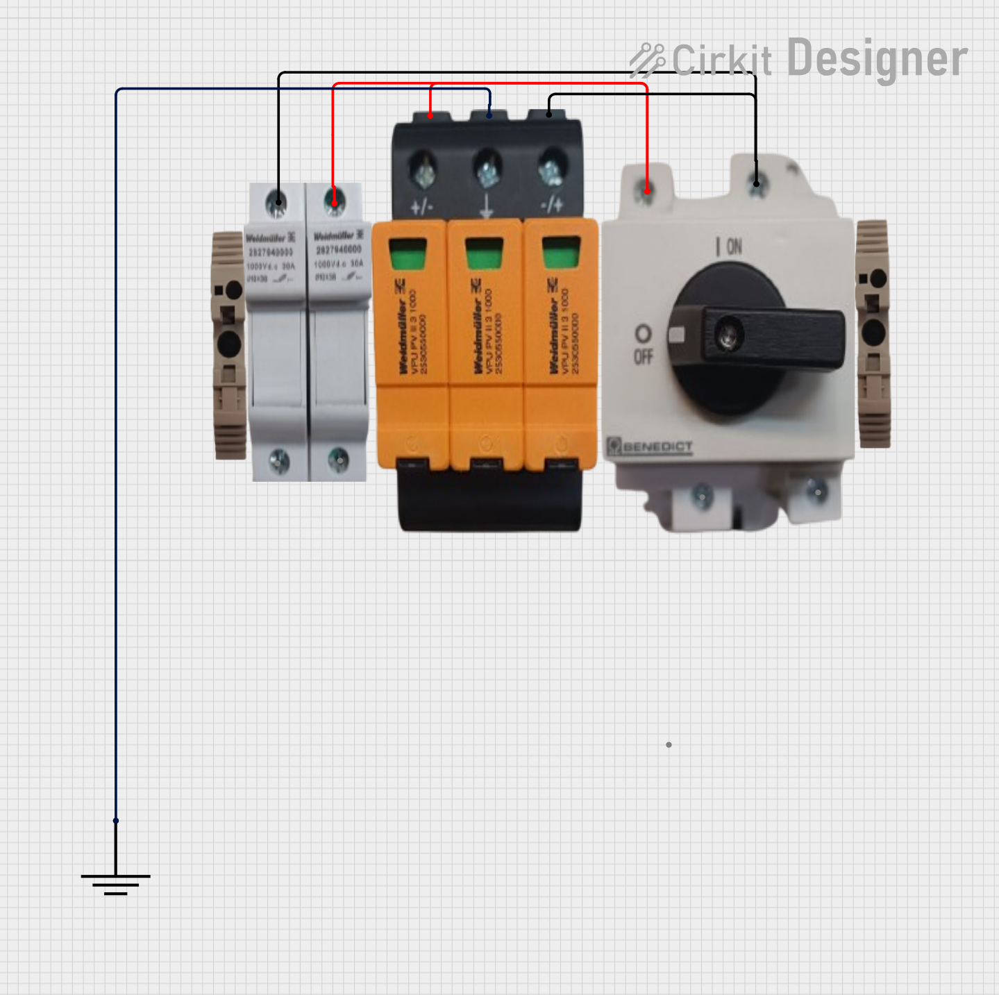 Open Project in Cirkit Designer
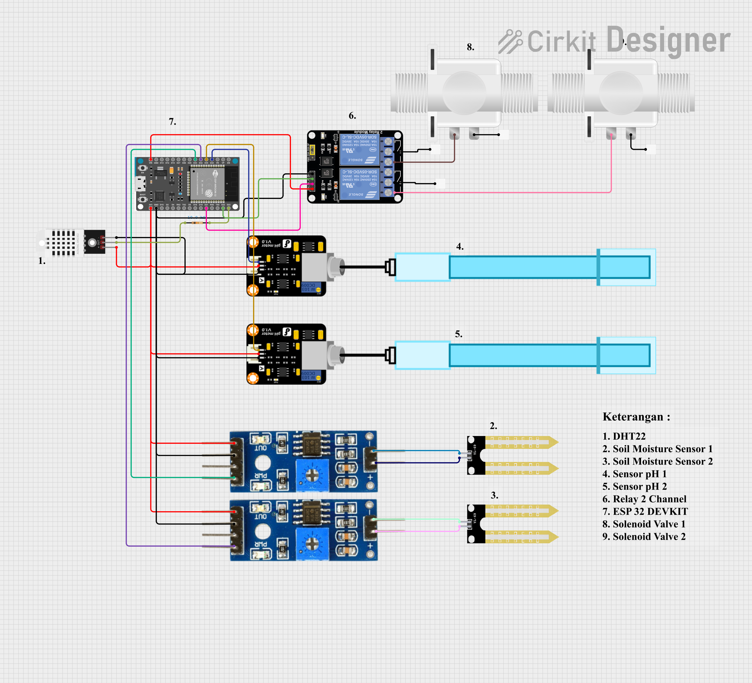 Open Project in Cirkit Designer
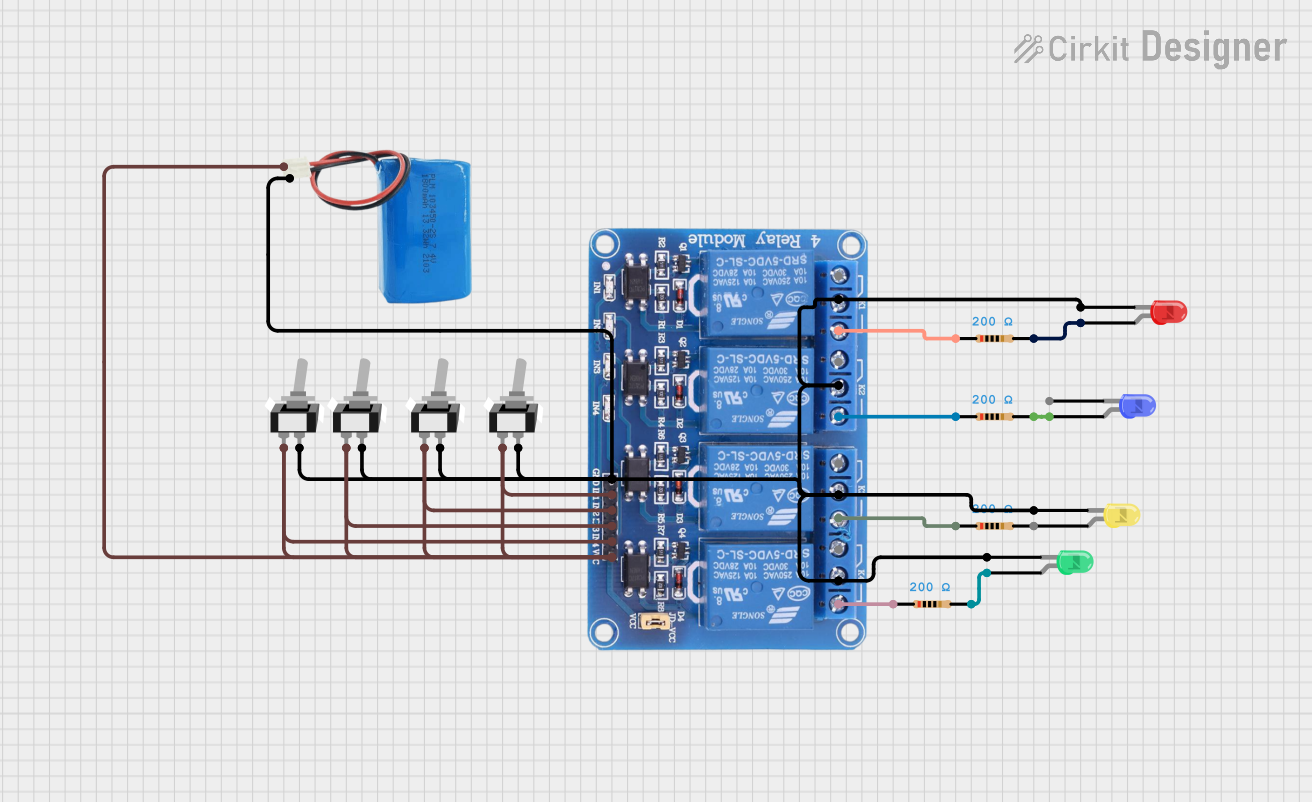 Open Project in Cirkit Designer
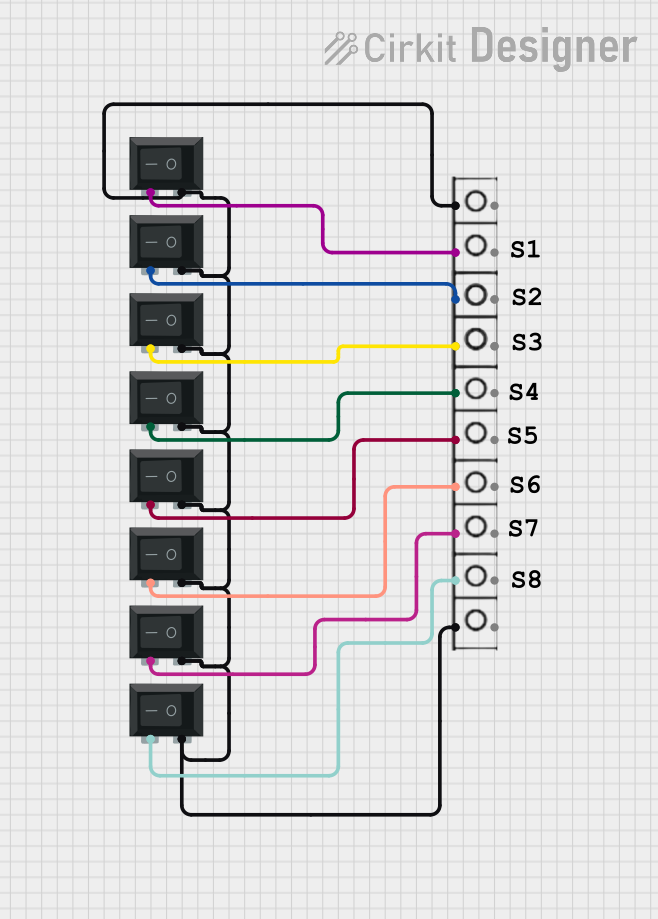 Open Project in Cirkit Designer
Explore Projects Built with spl 1:2
Open Project in Cirkit DesignerOpen Project in Cirkit DesignerOpen Project in Cirkit DesignerOpen Project in Cirkit DesignerCommon Applications and Use Cases
- Audio signal distribution to multiple speakers or amplifiers
- Video signal splitting for monitors, projectors, or recording devices
- Signal duplication in testing and measurement setups
- Broadcasting and live event setups requiring multiple outputs from a single source
Technical Specifications
The SPL 1:2 is designed to handle a wide range of signal types while maintaining high fidelity. Below are the key technical details:
General Specifications
| Parameter | Value |
|---|---|
| Input Signal Type | Analog or Digital |
| Output Signal Type | Analog or Digital |
| Frequency Range | 20 Hz – 20 kHz (audio) |
| Impedance (Input/Output) | 75 Ω (video), 600 Ω (audio) |
| Signal Gain | 0 dB (unity gain) |
| Power Supply Voltage | 5V DC or 12V DC (model-specific) |
| Power Consumption | < 1W |
Pin Configuration and Descriptions
The SPL 1:2 typically has the following pin configuration:
Power and Signal Connections
| Pin Number | Label | Description |
|---|---|---|
| 1 | VCC | Positive power supply input (5V or 12V DC) |
| 2 | GND | Ground connection |
| 3 | IN | Signal input (audio or video) |
| 4 | OUT1 | Signal output 1 (equal to input signal) |
| 5 | OUT2 | Signal output 2 (equal to input signal) |
Usage Instructions
How to Use the SPL 1:2 in a Circuit
- Power Connection: Connect the VCC pin to a 5V or 12V DC power source, depending on the model. Ensure the GND pin is connected to the ground of the power supply.
- Signal Input: Connect the input signal source (e.g., audio player, video source) to the IN pin.
- Signal Outputs: Connect the devices requiring the signal (e.g., speakers, monitors) to the OUT1 and OUT2 pins.
- Verify Connections: Double-check all connections to ensure proper operation and avoid signal loss or distortion.
Important Considerations and Best Practices
- Impedance Matching: Ensure that the input and output devices have compatible impedance to avoid signal degradation.
- Power Supply: Use a stable and noise-free power supply to prevent interference in the signal.
- Cable Quality: Use high-quality cables for both input and output connections to maintain signal integrity.
- Signal Type: Verify that the SPL 1:2 is compatible with the signal type (analog or digital) being used.
Example: Connecting SPL 1:2 to an Arduino UNO
The SPL 1:2 can be used with an Arduino UNO to split an audio signal generated by the Arduino. Below is an example code snippet for generating a simple audio tone:
// Example code for generating a tone using Arduino UNO
// This signal can be split using the SPL 1:2 component

const int audioPin = 9; // Pin connected to the SPL 1:2 IN pin

void setup() {
  pinMode(audioPin, OUTPUT); // Set the audio pin as an output
}

void loop() {
  // Generate a 1 kHz tone for 500 ms
  tone(audioPin, 1000, 500);
  delay(1000); // Wait for 1 second before repeating
}
Note: Connect the audioPin (pin 9) of the Arduino to the IN pin of the SPL 1:2. The OUT1 and OUT2 pins can then be connected to two separate audio devices.
Troubleshooting and FAQs
Common Issues and Solutions
No Signal at Outputs:
- Cause: Incorrect power supply connection.
- Solution: Verify that the VCC and GND pins are properly connected to a compatible power source.
Signal Degradation or Noise:
- Cause: Poor-quality cables or interference from nearby devices.
- Solution: Use shielded cables and keep the SPL 1:2 away from high-frequency devices.
Unequal Signal Levels at Outputs:
- Cause: Impedance mismatch between the output devices.
- Solution: Ensure both output devices have similar impedance ratings.
Overheating:
- Cause: Excessive power supply voltage or prolonged use in a high-temperature environment.
- Solution: Use the recommended power supply voltage and ensure proper ventilation.
FAQs
Q1: Can the SPL 1:2 handle both audio and video signals simultaneously?
A1: No, the SPL 1:2 is designed to handle one signal type at a time. Use separate units for audio and video signals.
Q2: Does the SPL 1:2 amplify the signal?
A2: No, the SPL 1:2 operates at unity gain (0 dB), meaning it does not amplify or attenuate the signal.
Q3: Can I use the SPL 1:2 with a battery-powered setup?
A3: Yes, as long as the battery provides the required voltage (5V or 12V DC) and sufficient current.
Q4: Is the SPL 1:2 compatible with HDMI signals?
A4: No, the SPL 1:2 is not designed for HDMI signals. Use an HDMI splitter for such applications.