How to Use Stepper: Examples, Pinouts, and Specs
Introduction
The McMaster 627T1 Stepper Motor is a precision electric motor designed to divide a full rotation into a large number of discrete steps. This allows for highly accurate control of position, speed, and acceleration. Unlike traditional DC motors, stepper motors do not require feedback systems for position control, making them ideal for applications where precise movement is critical.
Explore Projects Built with Stepper
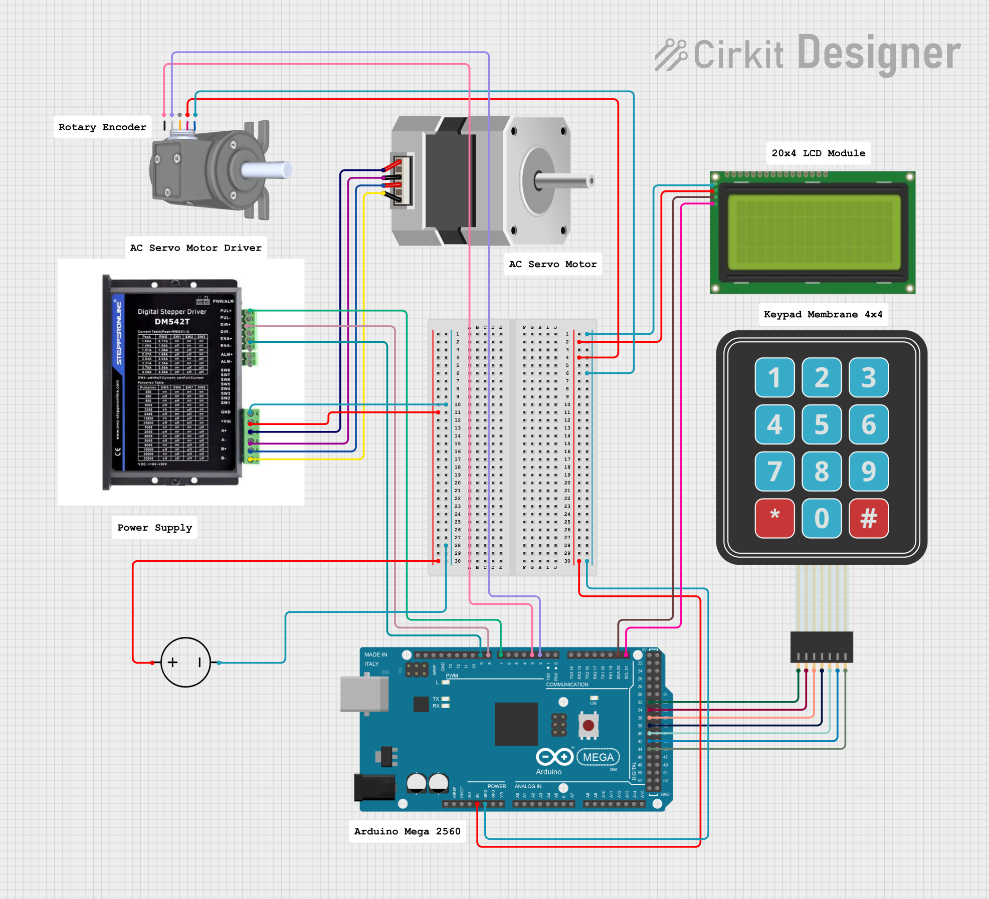
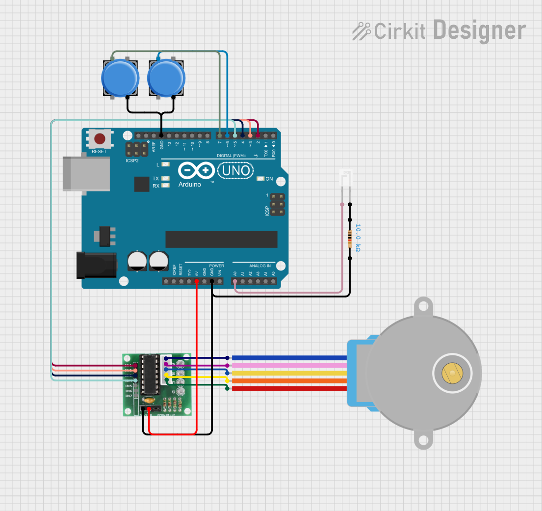
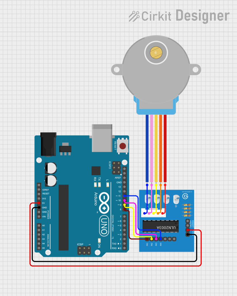
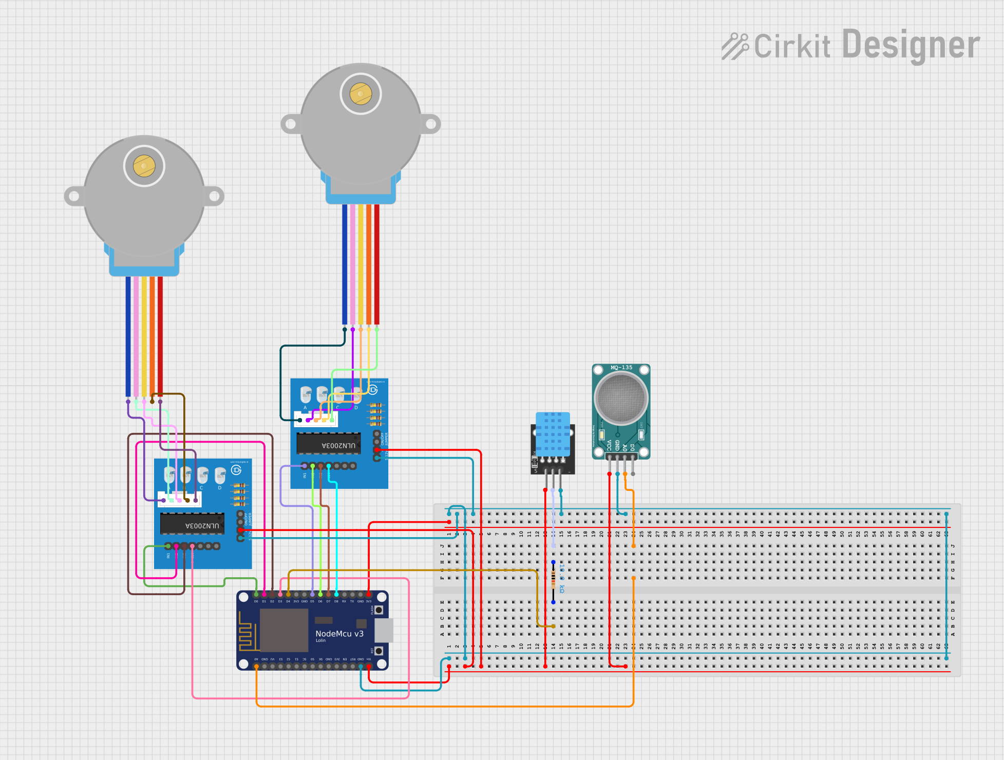
Explore Projects Built with Stepper
Common Applications
- 3D printers
- CNC machines
- Robotics
- Camera gimbals
- Automated conveyor systems
- Industrial automation
Technical Specifications
The McMaster 627T1 Stepper Motor is a bipolar stepper motor with the following key specifications:
| Parameter | Value |
|---|---|
| Manufacturer | McMaster |
| Part ID | 627T1 |
| Step Angle | 1.8° per step |
| Number of Steps per Rev | 200 steps |
| Rated Voltage | 12V |
| Rated Current per Phase | 1.5A |
| Holding Torque | 4.2 kg-cm (58 oz-in) |
| Shaft Diameter | 5 mm |
| Motor Type | Bipolar |
| Wiring Configuration | 4-wire |
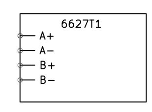
Pin Configuration and Descriptions
The McMaster 627T1 Stepper Motor has four wires for its bipolar configuration. The table below describes the wiring:
| Wire Color | Function | Description |
|---|---|---|
| Red | Coil A+ | Positive terminal of Coil A |
| Blue | Coil A- | Negative terminal of Coil A |
| Green | Coil B+ | Positive terminal of Coil B |
| Black | Coil B- | Negative terminal of Coil B |
Usage Instructions
How to Use the Stepper Motor in a Circuit
Connect the Motor to a Driver:
Use a stepper motor driver (e.g., A4988 or DRV8825) to control the motor. The driver will handle the current and voltage requirements of the motor.Power Supply:
Ensure the power supply matches the motor's rated voltage (12V) and can provide sufficient current (at least 1.5A per phase).Microcontroller Interface:
Connect the stepper motor driver to a microcontroller (e.g., Arduino UNO) to send step and direction signals.Wiring Example:
- Connect the motor wires to the driver as per the pin configuration.
- Connect the driver's step and direction pins to the microcontroller's digital pins.
- Provide power to the driver and motor.
Arduino UNO Example Code
Below is an example code to control the McMaster 627T1 Stepper Motor using an A4988 driver and an Arduino UNO:
// Define pins for step and direction
const int stepPin = 3;  // Pin connected to the driver's STEP input
const int dirPin = 4;   // Pin connected to the driver's DIR input

void setup() {
  pinMode(stepPin, OUTPUT); // Set step pin as output
  pinMode(dirPin, OUTPUT);  // Set direction pin as output

  digitalWrite(dirPin, HIGH); // Set initial direction (HIGH = clockwise)
}

void loop() {
  // Rotate the motor one full revolution (200 steps for 1.8° step angle)
  for (int i = 0; i < 200; i++) {
    digitalWrite(stepPin, HIGH); // Generate a step pulse
    delayMicroseconds(1000);    // Wait 1 ms (adjust for speed control)
    digitalWrite(stepPin, LOW); // End the step pulse
    delayMicroseconds(1000);    // Wait 1 ms
  }

  delay(1000); // Wait 1 second before changing direction

  // Change direction
  digitalWrite(dirPin, !digitalRead(dirPin)); // Toggle direction pin
}
Important Considerations and Best Practices
- Current Limiting: Adjust the current limit on the stepper driver to match the motor's rated current (1.5A per phase) to prevent overheating.
- Microstepping: Enable microstepping on the driver for smoother motion and reduced noise.
- Cooling: Use a heat sink or fan for the driver if operating at high currents for extended periods.
- Power Supply: Use a regulated power supply to avoid voltage spikes that could damage the motor or driver.
Troubleshooting and FAQs
Common Issues and Solutions
Motor Not Moving:
- Check the wiring between the motor, driver, and microcontroller.
- Ensure the power supply is connected and providing the correct voltage.
- Verify that the step and direction signals are being sent from the microcontroller.
Motor Vibrates but Does Not Rotate:
- Ensure the wiring matches the correct coil pairs (e.g., Red-Blue for Coil A, Green-Black for Coil B).
- Check the stepper driver settings for microstepping and current limit.
Overheating:
- Reduce the current limit on the driver.
- Ensure proper ventilation or add a cooling system.
Inconsistent or Jerky Motion:
- Enable microstepping on the driver.
- Verify that the step pulse timing is consistent in the code.
FAQs
Q: Can I use a different voltage power supply?
A: The motor is rated for 12V, but you can use a higher voltage with a compatible driver. Ensure the driver regulates the current to prevent damage.
Q: What is the maximum speed of the motor?
A: The maximum speed depends on the step pulse frequency and load. Experiment with different delay values in the code to find the optimal speed.
Q: Can I use this motor with a unipolar driver?
A: No, the McMaster 627T1 is a bipolar stepper motor and requires a bipolar driver.
Q: How do I identify the coil pairs?
A: Use a multimeter to measure resistance. The two wires with measurable resistance belong to the same coil.
By following this documentation, you can effectively integrate the McMaster 627T1 Stepper Motor into your projects for precise and reliable motion control.